Using NXP SDK with Teensy 4.0
Intro
There’s a new Teensy in the town. It’s the new Teensy 4.0 and it’s a small beast. Well, as you probably already know, Teensy boards are not only famous because of their nice small factor boards and their Arduino compatibility, but also because of the ecosystem around them. There are so many tools and libraries for them that you can implement complex projects in a very short time.
Currently, you can use Teensy 4.0 only with the Arduino library and environment. That’s great of course, but if you follow this blog for some time, then you know me already. I like the low level peripheral libraries and CMSIS when I do my stupid projects.
Anyway, a couple of days ago I’ve ordered my Teensy 4.0 from PJRC and it actually arrived very fast, but I just found time today to play with it. First thing was to test that it works, so I’ve connected it and I’ve seen the LED flashing. Then followed the instructions and installed Arduino IDE and the support tools for Teensy and a few minutes later I verified that also the USB-CDC works and I could get messages on my terminal.
I also have Teensy 3.1, 3.5 and 3.6 and as a matter of fact, I’ve used Teensy 3.2 in this project here with the MPU-6050 in order to control a 3D object inside Unity3D. But that project was done using the Arduino library and it was implemented fast as the USB raw lib works stable on Teensy.
Anyway, back to Teensy 4.0, the next step was to use PlatformIO and also tested it there, so I’ve connected the PCM5102A board I’ve also used in this post and in just few minutes I verified that I was getting a sin signal on the DAC’s output. All great.
So, final thing was to find what SDK NXP provides for imxrt1062 and try to build an example.
But…
after some search I’ve found that the MCU that Teensy uses doesn’t have an internal flash but an external SPI NOR. Then I start wondering what’s going on, because I wasn’t familiar with the new imxrt1062 MCU (yep, it’s common for me to just order dev boards without RTFM first). Then a friend text me and I told him what I was doing and he got triggered also and start looking on the Teensy 4.0, then at some point he told me that there was another Cortex-M0 on the board and later at some point I also had a look in the schematics and all became clear. BTW kudos for having the schematics open, that’s really cool.
So at that point, I knew that the bootloader is hardcoded and running actually on the external Cortex-M0 and that the bootloader uploads the firmware on the external NOR. Then I’ve looked in the source code of the Arduino core for teensy in github and I’ve seen that there is a custom bootdata.c file instead of the startup files that I’m used to for ARM Cortex-M. Yes, of course I know that you can write your own startup code in C (or asm), but so far I was always using some CMSIS peripheral libraries that come with an asm startup file, which sets up the IVT in the RAM and them pass execution to main.
So, I’ve decided to download the SDK for the imxrt1062 from here. Then I got interrupted (highest priority) from my 1.5 year old son and stopped all activities for several hours… When I got back at night, I’ve extracted the SDK and found out that actually there are startup files and the SDK is very similar to the Standard peripheral drivers library from STM, which was a good sign. So the next question was how to build a firmware that works on the Teensy using the SDK.
During that time I’ve asked a question on the PJRC forum and received the answer that there isn’t such a thing. That triggered a challenge inside me, of course, but on the other hand I don’t have much free time, so my initial thought was just to leave it be. Then Paul Stoffregen came and did a very brief description of the architecture and he gave me the two hints that actually made everything clear. The first was that the bootloader doesn’t do any magic (e.g. encryption, setting up the environment, e.t.c.) and the second that the firmware needs to contain a 512 bytes header with the boot data sector and the IVT.
When I’ve read that I smiled, because that means that since the bootloader doesn’t do any exotic things to bring up the CPU then it means that the the CPU starts from reset state and starts reading from the NOR. At that point I didn’t care for any other details, because that meant that the things were much easier than I initially thought and I thought lets try build any firmware using the SDK and upload it to the NOR using the Teensy bootloader. Later, also Paul verified my assumption.
Therefore in the next part I’ll explain how to use the NXP SDK and CMSIS to build a firmware and upload it on the Teensy 4.0.
Prerequisites
The following guide is tested on Linux (Ubuntu 18.04), but I’ve decided to use my CDE Docker image that I’ve introduced in the DevOps for Embedded post series. This makes things easier also for those who run Windows, but I haven’t tested that on Windows so I don’t know if it works.
Therefore, you need at least to install Docker or use an Ubuntu VM if you don’t have Linux and the docker image doesn’t work on your Windows machine (which I can’t think why this can happen, but anyway).
Build the SDK examples
First you need to download the SDK for imxrt1062 from here. Since there’s no direct link you need to browse in Processors -> i.MX -> RT -> MIMXRT1060 -> MIMXRT1062xxxxA and when it comes to select which packages you want in your SDK then just select all. After the SDK is downloaded then extract it to any folder you want. Here I’ll assume that the folder you’re using will be the ~/Downlads/SDK_2.7.0_MIMXRT1062xxxxA. Therefore inside this folder you should see this directory tree:
1
2
3
4
5
6
7
8
9
10
boards
CMSIS
components
devices
docs
middleware
MIMXRT1062xxxxA_manifest_v3_6.xml
rtos
SW-Content-Register.txt
tools
Now cd to this directory:
1
cd ~/Downloads/SDK_2.7.0_MIMXRT1062xxxxA/boards/evkmimxrt1060/driver_examples/gpio/led_output/armgcc
This is the hello-world example code that simply toggles a gpio. If that works, then everything else should work, because that means that the CPU and the needed peripherals will get configured and since the SDK libs are based on CMSIS then all I need is working.
Here you need to have in mind that this SDK is based on another development this board from NXP. Therefore the BSP is tailored for the MIMXRT1060-EVK board. This means that you need to take care of any differences between the Teensy pinout and the EVK for the example codes. For this reason you need to change the EXAMPLE_LED_GPIO_PIN definition in the code in the gpio_led_output.c file.
The pinout for Teensy 4.0 is here. From this table you can see that GPIO1.25 is the pin 23 on the Teensy board therefore in the gpio_led_output.c file you need to make this change:
1
#define EXAMPLE_LED_GPIO_PIN (25U)
That means that now the LED pin (from the codes perspective) will be the pin 23. I didn’t use actual Teensy’s LED pin because I wanted to verify the result with the oscilloscope. After you do this change, you’re actually done… Now you need to build the project.
The good thing is that NXP is using CMake! Thanks NXP. ST please keep notes. On the other hand the cmake files are tailored for the specific SDK examples, but nevertheless is better than nothing. I won’t go into the details on how cmake works, but in order to build the firmware you need to trigger the build inside the armgcc folder. Let me repeat the full path, just in case:
1
~/Downloads/SDK_2.7.0_MIMXRT1062xxxxA/boards/evkmimxrt1060/driver_examples/gpio/led_output/armgcc
Now assuming that you have Docker installed, open a terminal in your host, change to the armgcc folder and run this fugly command:
1
2
3
4
5
6
docker run --rm -it \
  -v /home/$(whoami)/Downloads/SDK_2.7.0_MIMXRT1062xxxxA:/tmp \
  -w=/tmp/boards/evkmimxrt1060/driver_examples/gpio/led_output/armgcc \
  dimtass/stm32-cde-image:0.1 \
  -c "ARMGCC_DIR=/opt/toolchains/gcc-arm-none-eabi-9-2019-q4-major/ \
  ./build_all.sh"
Yes, I know. That’s a monstrous one-liner, but if I explain what it does you’ll see that it’s quite simple. The above command will run a container using the dimtass/stm32-cde-image:0.1 image. It will then mount the SDK top dir folder in the container’s /tmp folder and it will change the working dir to the armgcc folder that you currently are. Then inside the container will just run this command:
1
ARMGCC_DIR=/opt/toolchains/gcc-arm-none-eabi-9-2019-q4-major/ ./build_all.sh
You can make a bash script to avoid using this long command. Anyway, this will build the cmake project and you’ll get this output in the end:
1
2
3
[ 95%] Building C object CMakeFiles/igpio_led_output.elf.dir/tmp/devices/MIMXRT1062/utilities/fsl_sbrk.c.obj
[100%] Linking C executable flexspi_nor_release/igpio_led_output.elf
[100%] Built target igpio_led_output.elf
Then you’ll see some new folders and one of them is called flexspi_nor_release. Inside this folder you’ll find the igpio_led_output.elf firmware. Last step is to convert the elf executable to a HEX file. You can use docker again for this by running another fugly command:
1
2
3
4
5
docker run --rm -it \
  -v /home/$(whoami)/Downloads/SDK_2.7.0_MIMXRT1062xxxxA:/tmp \
  -w=/tmp/boards/evkmimxrt1060/driver_examples/gpio/led_output/armgcc \
  dimtass/stm32-cde-image:0.1 \
  -c "/opt/toolchains/gcc-arm-none-eabi-9-2019-q4-major/bin/arm-none-eabi-objcopy -O ihex flexspi_nor_release/igpio_led_output.elf flexspi_nor_release/igpio_led_output.hex"
The above command will just execute this command inside the docker container:
1
/opt/toolchains/gcc-arm-none-eabi-9-2019-q4-major/bin/arm-none-eabi-objcopy -O ihex flexspi_nor_release/igpio_led_output.elf flexspi_nor_release/igpio_led_output.hex
That’s just the objcopy of the docker image gcc toolchain that converts the elf file to hex. That’s it! You can also add another target in the cmake to do this automatically, but for now it doesn’t matter.
Now, you need to either run the Teensy GUI and load that hex file or use teensy_loader_cli. In my case I’ve used the CLI like this:
1
teensy_loader_cli -v -w --mcu=imxrt1062 flexspi_nor_release/igpio_led_output.hex
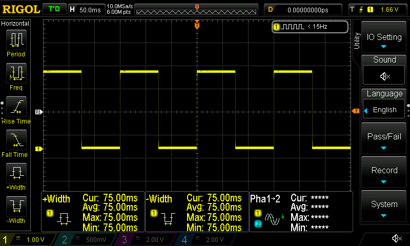
Then connect the oscilloscope probe on the pin 23, connect the USB cable from your host to Teensy while holding the reset button on the board and then release the button. If all goes properly, you should see this output:
1
2
3
4
5
6
7
8
Teensy Loader, Command Line, Version 2.1
Read "flexspi_nor_release/igpio_led_output.hex": 9496 bytes, 0.5% usage
Waiting for Teensy device...
 (hint: press the reset button)
Found HalfKay Bootloader
Read "flexspi_nor_release/igpio_led_output.hex": 9496 bytes, 0.5% usage
Programming...........
Booting
Also on the oscilloscope you should see this
Now, just to be sure, that also code changes work then in the gpio_led_output.c file change the time constant value in the SDK_DelayAtLeastUs() and remove one zero, so it becomes:
1
SDK_DelayAtLeastUs(10000, SDK_DEVICE_MAXIMUM_CPU_CLOCK_FREQUENCY);
Now, re-build and re-flash and you should see something like this:
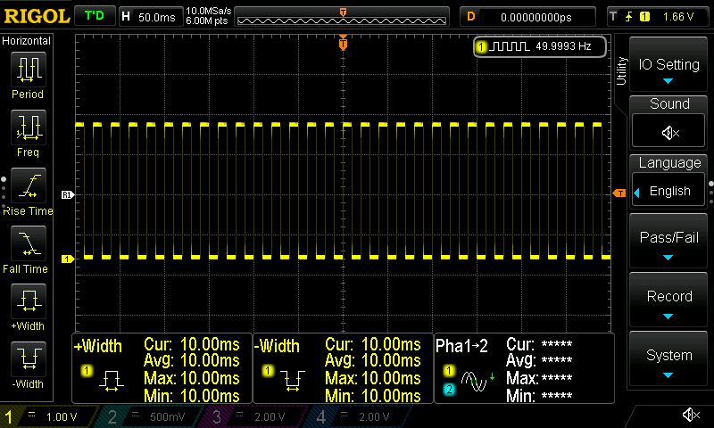
OK, now you’re sure that it works.
Conclusion
So, in this post I’ve explained how you can use the SDK peripheral library (which is based on the CMSIS) to build a firmware that runs on Teensy 4.0. The good thing is that it seems that is working fine, but I haven’t checked other examples other than the gpio. The next thing for me is to create a cmake template like those I have for the various STM32 MCUs and I’m using in other projects that I post here. To do that I’ll use the current CMake files as a base, but pretty much I’ll have to re-write most of it.
The reason I’m not using the current cmake project from the SDK is that it’s based on another dev-kit, also the current cmake files target the current SDK’s file hierarchy and libraries and of course the size of the current SDK is huge to use as a template. So I’ll strip this down to a minimal template for my future projects. The I need to think about another stupid project. Anyway, I hope that more people find this useful.
Have fun!
Comments powered by Disqus.