Controlling a 3D object in Unity3D with teensy and MPU-6050
Intro
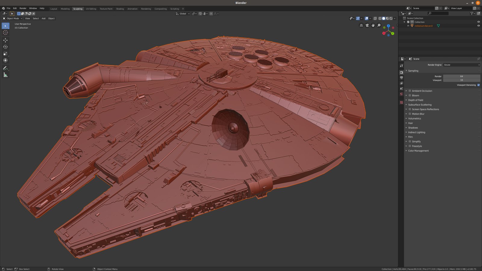
Have a look at this image.

What does it look like? Is it the new Star Wars? Nope. It’s a 3D real time rendering from a game that I’ve build just to test my new stupid project with the MPU6050 motion tracking sensor. Cool isn’t it? Before I get there let me do a short introduction.
The reason I’ve enjoyed this project so much, is that I’ve started this project without knowing anything about 3D game engines, skyboxes and quaternions and after 1.5 day I got this thing up and running! I don’t say this to praise myself. On the contrary, I mention this to praise the current state of the free and open source software. Therefore, I’ll use some space here to praise the people that contribute to FOSS and make for others easy and fast to experiment and prototype.
I don’t know for how long you’ve been engineers, hobbyists or anything related and for how long. But from my experience, trying to make something similar 15 or 10 years ago (and also on a Linux machine), would be really hard and time spending procedure. Of course, I don’t mean getting the same 3D results, I mean a result relative to that era. Maybe I would spend several months, because I would have to do almost everything by myself. Now though, I’ve only wrote a few hundred lines of glue code and spend some time on YouTube and surfing github and some other sources around the web. Nowadays, there are so many things that are free/open and available that is almost impossible not to find what you’re looking for. I’m not only talking about source code, but also tools, documentation, finished projects and resources (even open hardware). There are so many people that provide their knowledge and the outcome of their work/research nowadays, that you can find almost everything. You can learn almost everything from the internet, too. OK, probably it’s quite difficult to become a nuclear physicist using only online sources, but you can definitely learn anything related to programming and other engineering domains. It doesn’t matter why people decide to make their knowledge available publicly, all it matters is that it’s out there, available for everyone to use it.
And thanks to those people, I’ve managed to install Unity3D on my Ubuntu, learn how to use it to make what I needed, found a free to use 3D model for the Millennium Falcon, used Blender on Linux to edit the 3D model, found a tool to create a Skybox that resembles the universe, found an HID example for the teensy 3.2, the source code for the MPU6050 and how to calibrate it and finally dozens of posts with information about all those things. Things like how to use lens flares, mesh colliders to control flare visibility on cameras with flare layers, event system for GUI interactions and several other stuff that I wasn’t even aware of before, everything explained from other people in forums in a way that it’s far easier to read from any available documentation. Tons of information.
Then I just put all the pieces together and wrote the glue code and this is the result.
(Excuse, the bad video quality, but I’ve used my terrible smartphone camera)
It is a great time to be an engineer or a hobbyist and having all those tools and information available to your hands. All you need is just some time for playing and making stupid projects 😉
All the source code and files for this project are available here:
https://github.com/dimtass/teensy-hid-with-unity3d
Note: This post is not targeting 3D graphics developers in no way. It’s meant mostly for embedded engineers or hobbyists.
So, let’s dive into the project…
Components
To make the project I’ve used various software tools and only two hardware components. Let’s see the components.
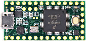
Teensy 3.2
You’re not limited on Teensy 3.2, but you can use any Teensy that supports the RawHID lib. Teensy 3.2 it’s based on the NXP MK20DX256VLH7 which has a Cortex-M4 core running at 72 MHz and can be overclocked easily using the Arduino IDE up to 96MHz. It has various of peripherals and the pinout exports everything you need to build various interesting projects. For this project I’ve only used the USB and I2C. Teensy is not the cheapest MCU board out there as it costs around $20, but it comes with a great support and it’s great for prototyping.
MPU-6050
According to TDK (which manufactures the MPU-6050) this is a Six-Axis (Gyro + Accelerometer) MEMS MotionTracking Devices which has an onboard Digital Motion Processor (DMP). According the TDK web page I should use a ™ on every word less than 4 characters in the previous sentence. Anyway, to put it simple it’s a package that contains a 3-axis Gyro, a 3-axis Accelerometer and a special processing unit that performs some complex calculations on the sensor’s data. You can find small boards with the sensor on ebay that cost ~1.5 EUR, which is dirt cheap. The sensor is 3V3 and 5V capable, which makes it easy to be used with a very wide range of development boards and kits.

Connecting the hardware
The hardware connections are easy as both the Teensy and the mpu-6050 are voltage level compatible. The following table shows the connections you need to make.
| Teensy 3.2 (pin) | MPU-6050 |
| 3V | VCC |
| GND | GND |
| 18 | SDA |
| 19 | SCL |
| 23 | INT |
That’s it, you’re done. Now all you have to do, is to connect Teensy 3.2 to your workstation, calibrate the sensor and then build the firmware and flash it.
Calibrating the MPU-6050
Not all the MPUs are made the same. Since it’s a quite complex device, both the gyro and the accelerometer (accel) have tolerances. Those tolerances affect the readings you get, for example if you place the sensor on a perfectly flat space then you’ll get a reading from the sensor that it’s not on a flat space, which means that you’re reading the tolerances (offsets). Therefore, first you need to place the sensor on a flat space and then use the readings to calibrate the sensor and minimize those offsets. Because every chip has different tolerances, you need to do this for every sensor, so you don’t do this once for a single sensor and then re-use the same values also for others (even if they are in the same production batch). This sensor supports to upload to it those offset values using some I2C registers in order to perform calculations with those offsets, which in the end offloads the external CPU.
Normally, if you need maximum accuracy during calibration, then you need an inclinometer in order to place your sensor completely flat and a vibration free base. You can find inclinometers on ebay or amazon, from 7 EUR up to thousands of EUR. Of course, you get what you pay. Have in mind that an inclinometer is just a tilt sensor, but it’s calibrated in the production. A cheap inclinometer may suck in many different ways, e.g. maybe is not even calibrated or the calibration reference is not calibrated or the tilt sensor itself is crap. Anyway, for this project you don’t really need to use this.
For now just place the sensor in a surface that seems flat. Also because you probably have already soldered the pin-headers, try to flatten the sensor compare to the surface. We really don’t need accuracy here, just an approximation, so make your eye an inclinometer.
Another important thing to know is that when you power-up the sensor then the orientation is zeroed at the current orientation. That means if the sensor is pointing south then this direction will always be the starting point. This is important for when you connect the sensor to the 3D object, then you need to put the sensor flat and pointing to that object on your screen and then power-on (connect the USB cable to Teensy).
Note: Before you start the calibration you need to leave the module powered on for a few minutes in order for the temperature to stabilize. This is very important, don’t skip this step.
OK, so now you should have your sensor connected to Teensy and on a flat(-ish) surface. Now you need to need to flash the calibration firmware. I’ve included two calibration source codes in the repo. The easiest one to use is in mpu6050-calibration/mpu6050-raw-calibration/mpu6050-raw-calibration.ino. I’ve got this source code from here.
Note: In order to be able to build the firmware on the Arduino IDE, you need to add this library here. The Arduino library in this repo is for both the MPU-6050 and the I2Cdev which is needed from all the source codes. Just copy from this folder the I2Cdev and MPU6050 in to your Arduino library folder.
When you build and upload the mpu6050-raw-calibration.ino on the Teensy, then you also need to use the Arduino IDE to open the Serial Monitor. When you do that, then you’ll get this prompt repeatedly:
1
Send any character to start calibrating...
Press Enterin the output textbox of the Serial Monitor and the calibration will start. In my case there were a few iterations and then I got the calibration values in the output:
1
2
3
4
5
6
7
8
9
10
11
12
13
14
15
calibrating...
            ax	ay	az	gx	gy	gz
            ------------------------------------------------
average values:		-7	-5	16380	0	1	0
calibration offsets:	1471	-3445	1355	-44	26	26

MPU-6050 is calibrated.

Use these calibration offsets in your code:
mpu.setXAccelOffset(1471);
mpu.setYAccelOffset(-3445);
mpu.setZAccelOffset(1355);
mpu.setXGyroOffset(-44);
mpu.setYGyroOffset(26);
mpu.setZGyroOffset(26);
Now copy-paste the above code block in to your teensy-motion-hid/teensy-motion-hid.ino file in function setCalibrationValues().
As the message says, now just open the teensy-motion-hid/teensy-motion-hid.ino file and copy the mpu.set*function calls in the setCalibrationValues()function.
Advanced calibration
If you want to see a few more details regarding calibration and an example on how to use a PID controller for calibrating the sensor and then use a jupyter notebook to analyze the results, then continue here. Otherwise, you can skip this section as it’s not really needed.
In order to calculate the calibration offsets you can use a PID controller. For those who doesn’t know what PID controller is, then you’ll have to see this first (or if you know how negative feedback on op-amps works, then think that it’s quite the same). Generally, is a control feedback loop that is used a lot in control systems (e.g. HVAC for room temperature, elevators e.t.c).
Anyway, in order to calibrate the sensor using a PID controller, then you need to build and upload the mpu6050-calibration/mpu6050-pid-calibration/mpu6050-pid-calibration.ino source code. I won’t get in to the details of the code, but the important thing is that this code uses 6 different PID controllers, one for each offset you want to calculate (3 for the accel. axes and 3 for the gyro axes). This source code is a modification I’ve made of this repo here.
Again, you need to let the sensor a few minutes powered on before perform the calibration and set it on a flat surface. When the firmware starts, then it will spit out numbers on the serial monitor. Here’s an example:
1
2
3
4
5
6
7
8
9
10
11
12
13
14
15
16
17
18
19
20
-3516.3,877.9,8269.6,-2073.8,10956.8,810.3,80.9,-17.7,-47.9,10.6,-45.1,10.4
-3644.8,1062.6,8561.6,-2507.6,13018.4,981.2,86.3,-22.1,-53.1,13.4,-49.1,12.9
-2850.7,1201.4,6627.5,-2829.4,13759.5,1108.9,78.8,-26.1,-49.0,15.8,-47.7,15.3
-2014.7,1286.8,4647.2,-3025.8,14540.3,1187.0,66.1,-29.2,-38.7,17.5,-42.3,17.3
-1401.3,1344.7,3206.7,-3157.8,15097.3,1240.3,54.8,-31.7,-33.4,19.1,-32.6,18.7
-970.1,1384.5,2206.9,-3248.2,15496.5,1276.4,45.7,-33.8,-26.3,20.2,-29.6,20.1
-670.4,1412.2,1518.4,-3310.3,15777.1,1301.0,39.6,-35.6,-22.1,21.3,-25.5,21.3
-468.0,1431.5,1048.3,-3353.1,15970.9,1317.8,32.5,-37.1,-17.1,22.1,-18.1,22.1
-331.2,1445.3,716.5,-3382.3,16120.0,1328.2,27.6,-38.4,-12.7,22.6,-16.6,22.9
-231.5,1454.7,491.7,-3402.2,16194.1,1336.2,22.8,-39.4,-10.5,23.1,-11.3,23.4
-155.2,1461.0,339.7,-3416.1,16259.5,1341.1,20.3,-40.4,-9.9,23.6,-6.1,23.7
-104.5,1465.0,225.3,-3425.0,16301.3,1344.5,16.9,-41.2,-8.3,23.9,-13.3,24.5
-68.3,1467.7,152.0,-3431.1,16321.9,1347.3,13.1,-41.8,-9.1,24.4,-8.6,24.7
-42.4,1469.3,106.7,-3435.4,16338.1,1349.2,11.1,-42.3,-6.4,24.7,-4.6,24.8
-20.5,1470.2,75.5,-3438.7,16342.9,1351.1,9.6,-42.7,-7.5,25.0,-3.9,25.0
-21.9,1471.5,50.7,-3440.5,16348.5,1352.6,8.0,-43.1,-7.0,25.4,-4.3,25.2
-6.7,1471.5,36.5,-3441.9,16358.4,1353.9,7.3,-43.5,-5.1,25.6,-0.5,25.2
0.0,1471.3,16.5,-3442.6,16360.3,1354.8,6.8,-43.8,-3.1,25.7,0.3,25.2
-9.1,1472.0,17.3,-3443.5,16366.1,1355.6,5.3,-44.0,-1.3,25.7,-5.5,25.7
-6.1,1472.3,16.0,-3444.2,16370.7,1356.4,3.2,-44.1,-0.9,25.7,-4.8,25.8
And this goes on forever. Each line is a comma separated list of values and the meaning of those values from left to right is:
- Average Acc X value
- Average Acc X offset
- Average Acc Y value
- Average Acc Y offset
- Average Acc Z value
- Average Acc Z offset
- Average Gyro X value
- Average Gyro X offset
- Average Gyro Y value
- Average Gyro Y offset
- Average Gyro Z value
- Average Gyro Z offset
Now, all you need to do is to let this running for a couple of seconds (30-60) and then copy all the output from the serial monitor to a file named calibration_data.txt. The file actually already exists in the /rnd/github/teensy-hid-with-unity3d/mpu6050-calibration folder and it contains the values from my sensor, so you can use those to experiment or erase the file and put yours in its place. Also, be aware that when you copy the output from the serial monitor to the txt file, you need to delete any empty line in the end for the notebook scripts to work, otherwise, you’ll get an error in the jupyter notepad.
Note: while you running the calibration firmware you need to be sure that the there are no any vibrations on the surface. For example, if you put this on your desk then be sure that there’s no vibrations from you or any other equipment you may have running on the desk.
As I’m explaining quite thorough in the notebook how to use it, I’ll keep it simple here. Also, from this point I assume that you’ve read the jupyter notepad in the repo here.
You can use the notebook to visualize the PID controller output and also calculate the values to use for your sensor’s offsets. It’s interesting to see some plots here. As I mention in the notebook, you can use the data_start_offset and data_end_offset, to plot different subsets of data for each axis.
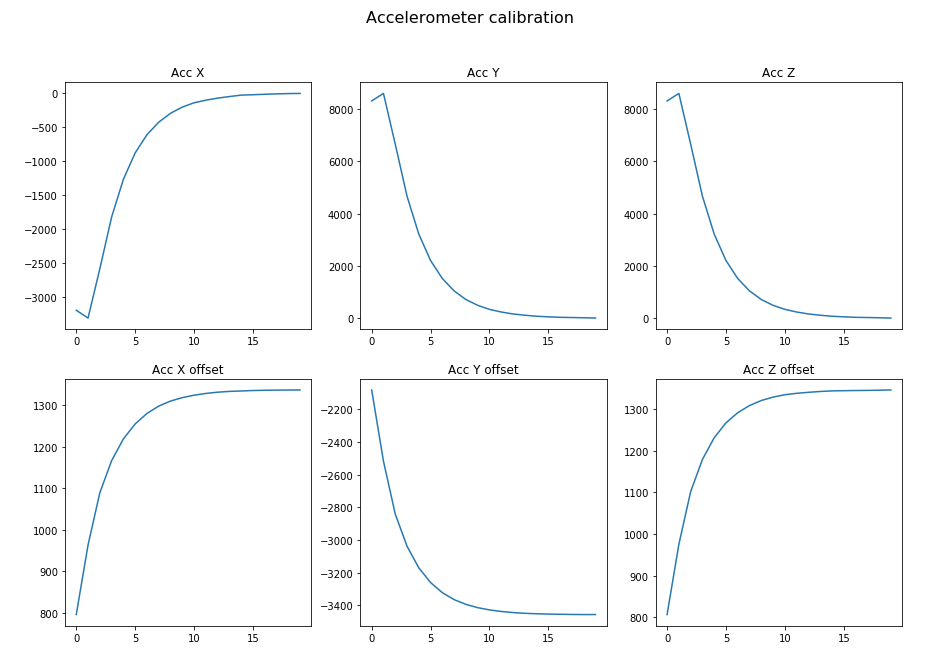
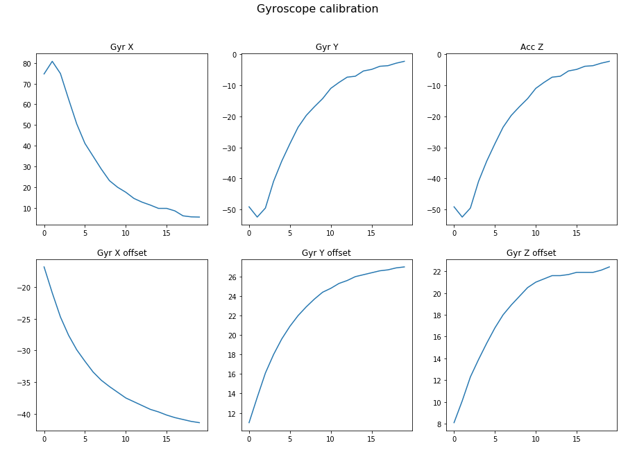
This is the plot when data_start_offset=0 and data_end_offset=20.
*Click on each image to zoom-in
So, as you can see in the first 20 samples, the PID controller kicks in and tries to correct the error and as the error in the beginning is significant, you get this slope. See in the first 15 samples the error for the Acc X axis is corrected from more than -3500 to near zero. For the gyro things are a bit different, as it’s more sensitive and fluctuates a bit more. Let’s see the same plots with data_start_offset=20 and data_end_offset=120.
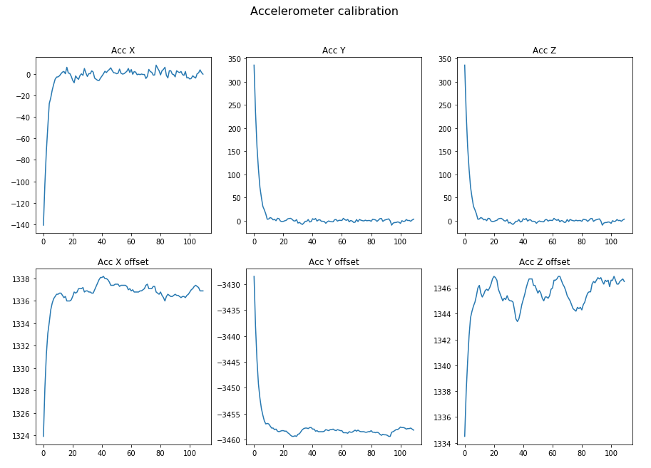

On the above images, I’ve started from sample 20, in order to remove the steep slope during the first PID controller input/output correction. Now you can see that the data that are coming from the accel. and gyro axes are fluctuating quite much and the PID tries on every iteration to correct this error. Of course, you’ll never get a zero error as the sensor is quite sensitive and there’s also thermal and electronic noise and also vibrations that you can’t sense but the sensor does. So, what you do in such cases is that you use the average value for each axis. Be careful, though. You don’t want to include the first samples in the average value calculations for each axis, because that would give you values that are way off. As you can see in the notepad here, I’m using the skip_first_n_data to skip the first 100 samples and then calculate the average from the rest values.
Finally, you can use the calculated values from the Source code values section and copy those in the firmware. You can use whatever method you like to calibrate the sensor, just be aware that if you try both methods you won’t get the same values! Even if you run the same test twice you won’t the exact same values, but they should be similar.
HID Manager
In the hid_manager/ folder you’ll find the source code from a tool I’ve written and I named hid_manager. Let me explain what this does and why is needed.
The HID manager is the software that receives the HID raw messages from Teensy and then copies the data in to a buffer that is shared with Unity. Note that this code works only for Linux. If you want to use the project on Windows then you need to port this code and actually is the only part of the project that is OS specific.
So, why use this HID manager? The problem with Unity3D and most similar software is that although they have some kind of input API, this is often quite complicated. I mean, I’ve tried to have a look at the API and try to use it, but quickly I’ve realized that it would take too much effort and time to create my own custom input controller for Unity and the use it in there. So, I’ve decided it to make it quick and dirty. In this case, though, I would say that quick and dirty, is not a bad thing (except that it’s OS specific). Therefore, what is the easiest and fast way to import real-time data to any other software that runs on the same host? Using some kind of inter-process communication, of course. In this case, the easiest way to do that was to use the Linux /tmp folder, which is mount in the system’s RAM memory and then create a file buffer in the /tmp and share this buffer between the Unity3D game application and the hid manager.
To do that I’ve written a script in hid_manager/start.sh, which makes sure to create this buffer and occupy 64 bytes in the RAM. The USB HID packets I’m using are 64 bytes long, so we don’t need more RAM than that. Of course, I’m not using all the bytes, but it’s good to have more than the exact the same number. For example, the first test was to send only the Euler angles from the sensor, but then I’ve realized that I was getting affected from the Gimbal lock effect, so I also had to add the Quaternion values, that I was getting anyways from the sensor (I’ll come back to those later). So, having more available size is always nice and actually in this case the USB packet buffer is always 64 bytes, so you get them for free. The problem arises when you need more than 64-byts, then you need to use some data serialization and packaging.
Also, note in both the teensy-motion-hid/teensy-motion-hid.ino and hid_manager/hid_manager.c, the indianness is the same, which makes things a bit easier and faster.
In order to build the code, just run make inside the folder and then you need first flash the Teensy with the teensy-motion-hid.ino firmware and then run the manager using the script.
1
./start.sh
If you try to run the script before the Teensy is programmed, then you’ll get an error as the HID device won’t be found attached and enumerated on your system.
Note: if the HID manager is not running then on the serial monitor output you’ll get this message
1
Unable to transmit packet
The HID manager supports two modes. The default mode is that it runs and it just copies the incoming data from the HID device to the buffer. The second one is the debug mode. In the debug mode, it prints also the 64 bytes that it gets from the Teensy. To run the HID manager in debug mode run this command.
1
DEBUG=1 ./start.sh
By running the above command you’ll get an output in your console similar to this:
1
2
3
4
5
6
7
8
9
10
11
12
13
14
15
16
17
18
19
20
21
22
23
24
25
26
27
28
29
30
$ DEBUG=1 ./start.sh
    This script starts the HID manager. You need to connect
    the teensy via USB to your workstation and flash the proper
    firmware that works with this tool.
    More info here:

    Usage for no debugging mode:
    $ ./start.sh

    Usage for debugging mode (it prints the HID incoming data):
    $ DEBUG=1 ./start.sh
Debug ouput is set to: 1
Starting HID manager...
Denug mode enabled...
Open shared memfile
found rawhid device

recv 64 bytes:
AB CD A9 D5 BD 37 4C 2B E5 BB 0B D3 BD BE 00 FC
7F 3F 00 00 54 3B 00 00 80 38 00 00 00 00 00 00
00 00 00 00 00 00 00 00 00 00 00 00 00 00 00 00
00 00 00 00 F9 29 00 00 01 00 00 00 E1 94 FF 1F

recv 64 bytes:
AB CD 9D 38 E5 3B 28 E3 AB 37 B6 EA AB BE 00 FC
7F 3F 00 00 40 3B 00 00 00 00 00 00 80 B8 00 00
00 00 00 00 00 00 00 00 00 00 00 00 00 00 00 00
00 00 00 00 F9 29 00 00 01 00 00 00 E1 94 FF 1F

...
The 0xAB 0xCD bytes are just a preamble.
Note: I haven’t added any checks on the data, like checking the preamble or having checksums e.t.c. as there wasn’t a reason for this. In other case I would consider at least a naive checksum like xor’ing the bytes, which is fast.
In the next video you can see on the left top side the quaternion data output from the Teensy and on the left bottom the raw hid data in the hid manager while it’s running in debug mode.
Of course, printing the data on both ends adds significant latency in model motion.
Teensy 3.2 firmware
The firmware for Teensy is located in teensy-motion-hid/teensy-motion-hid.ino. There’s no much to say here, just open the file with the Arduino IDE and then build and upload the firmware.
The important part in the code are those lines here:
1
2
3
4
5
6
7
8
9
10
11
12
13
14
15
16
17
18
mpu.dmpGetQuaternion(&q, fifoBuffer);

        un_hid_payload pl;
        pl.packet.preamble[0] = 0xAB;
        pl.packet.preamble[1] = 0xCD;

#ifdef ADD_EULER_TO_HID
        mpu.dmpGetEuler(euler, &q);
        pl.packet.x.number = euler[0] * 180 / M_PI;
        pl.packet.y.number = euler[1] * 180 / M_PI;
        pl.packet.z.number = euler[2] * 180 / M_PI;
#endif
#ifdef ADD_QUATERNION_TO_HID
        pl.packet.qw.number = q.w;
        pl.packet.qx.number = q.x;
        pl.packet.qy.number = q.y;
        pl.packet.qz.number = q.z;
#endif
If the ADD_EULER_TO_HID is enabled, then the Euler angles will also be added in the hid packet, but this might be add a bit more latency.
Now that the data are copied from Teensy to a shared memory buffer in /tmp, you can use Unity3D to read those data and use them in your game. Before proceed with the Unity3D section, though, let’s open a short parenthesis on the kind of data you get from the sensor.
Sensor data
As I’ve mentioned, the sensor does all the hard work and maths to calculate the Euler and the quaternion values from the 6 axes values in real-time (which is a great acceleration). But what are those values, why we need them and why I prefer to use only the quaternion? Usually I prefer to give just a quick explanation and leave the pros explain it better than me, so I’ll the same now.
The Euler angles is just the angle of the rotation for each axis in the 3D space. In air navigation those angles are known as roll, pitch and yaw and by knowing those angles you know your object’s rotation. You can see also this video which explains this better than I do. There’s one problem with Euler angles and this is that if two of the 3 axes are driven in a parallel configuration then you loose one degree of freedom. This is a video explains this in more detail.
As I’ve already mentioned, the sensor calculates the quaternion values. Quaternion is much more difficult to explain as it’s a 4-D number and anything more then 3-D is difficult to visualize and explain. I will try to avoid to explain this myself and just post this link here, which explains quaternions and try to represent them to the 3D space. The important thing you need to know, is that the quaternion doesn’t suffer from the gimbal lock, also it’s supported in Unity3D and it’s supposed to make calculations faster compared to vector calculations for the CPU/GPU.
Unity3D project
For this project I wanted to interact with a 3D object on the screen using the mpu-6050. Then I remembered that I’ve seen a video on Unity3D which seemed nice, so when I’ve seen that there was a Linux build (but not officially supported), then I thought to give it a try. When I’ve started the project I knew nothing about this software, but for doing simple things it seems nice. I had quite a few difficulties, but with some google-fu I’ve fixed all the issues.
Installing Unity3D on Ubuntu is not pain free, but it’s not that hard either and when you succeed, it works great. I’ve download the installer from here (see always the last post which has the latest version) and to install Unity Hub I’ve followed this guide here. Unity3D is not open source, but it’s free for personal use and you need to create an account in order to get your free license. I guess I could use an open 3D game machine, but since it was free and I wanted for personal use, I went for that. In order, to install the same versions that I’ve used run the following commands:
1
2
3
4
5
6
7
8
9
10
11
# install dependencies
sudo apt install libgtk2.0-0 libsoup2.4-1 libarchive13 libpng16-16 libgconf-2-4 lib32stdc++6 libcanberra-gtk-module

# install unity
wget http://beta.unity3d.com/download/292b93d75a2c/UnitySetup-2019.1.0f2
chmod +x UnitySetup-2019.1.0f2

# install unity hub
wget https://public-cdn.cloud.unity3d.com/hub/prod/UnityHubSetup.AppImage
chmod +x UnityHubSetup.AppImage
./UnityHubSetup.AppImage
When you open the project, you’ll find in the bottom tab some files. The one that’s interesting for you is the HID_controller.cs. This file in the repo is located in here: Unity3D-project/gyro-acc-test/Assets/HID_Controller.cs. In this file the important bits are the MemoryMappedfile object which is instantiated in the start() function and opens the shared file in the /tmp and reads the mpu6050 data and the update() function.
1
2
3
4
5
6
7
8
9
10
11
12
13
14
15
16
17
18
19
20
21
22
23
24
25
26
27
28
29
30
31
32
33
34
35
void Start()
{
    hid_buf = new byte[64];

    // transform.Rotate(30.53f, -5.86f, -6.98f);
    Debug.developerConsoleVisible = true;
    Debug.Log("Unity3D demo started...");

    mmf = MemoryMappedFile.CreateFromFile("/tmp/hid-shared-buffer", FileMode.OpenOrCreate, "/tmp/hid-shared-buffer");
    using (var stream = mmf.CreateViewStream()) {
        var data = stream.Read(hid_buf, 0, 64);
        if (data > 0) {
            Debug.Log("Data in: " + data);
            float hid_x = System.BitConverter.ToSingle(hid_buf, 2);
            Debug.Log("x: " + hid_x);
        }
    }


}

// Update is called once per frame
void Update()
{
    using (var stream = mmf.CreateViewStream()) {
        var data = stream.Read(hid_buf, 0, 64);
        if (data > 0) {
            float qw = System.BitConverter.ToSingle(hid_buf, (int) DataIndex.qW);
            float qx = System.BitConverter.ToSingle(hid_buf, (int) DataIndex.qX);
            float qy = System.BitConverter.ToSingle(hid_buf, (int) DataIndex.qY);
            float qz = System.BitConverter.ToSingle(hid_buf, (int) DataIndex.qZ);
            transform.rotation = new Quaternion(-qy, -qz, qx, qw);
        }
    }
}
As you can see in the start() function, the mmf MemoryMappedFile is created and attached to the /tmp/hid-shared-buffer. Then there’s a dummy read from the file to make sure that the stream works and prints a debug message. This code runs only once when the HID_Controller class is created.
In update() function the code creates a stream connected to the memory mapped file, then reads the data, parses the proper float values from the buffer and finally creates a Quaternion object with the 4D values and updates the object rotation.
You’ll also notice that the values in the quaternion are not in the (x,y,z,w) order, but (-y,-z,x,w). This is weird, right? But this happens for a couple of reasons that I’ll try to explain. In page 40 of this PDF datasheet you’ll find this image.
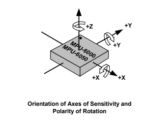
These are the X,Y,Z axes on the chip. Notice also the signs, they are positive on the direction is shown and negative on the opposite direction. The dot on the top corner indicated where pin 1 is located on the plastic package. The next image is the stick I’ve made with the sensor board attached on it on which I’ve drawn the dot position and the axes.

Therefore, you see that the X and Y axes are swapped (compared to the pdf image), so the quaternion from (x,y,z,w) becomes (y,x,z,w). But wait… in the code is (-y,-z,x,w)! Well, that troubled me also for a moment, then I’ve read this in the documentation,
Most of the standard scripts in Unity assume that the y-axis represents up in your 3D world.
which means that you need also to swap Y and Z, but because in the place of Y now is X, then you replace X with Z, so the quaternion from (y,x,z,w) becomes (y,z,x,w). But wait! What about the - signs? Well if you see again the first image it shows the sign for each axis. Because of the way you hold the stick, compared to the moving object on the screen reverses that rotation for the y and z axes, then the quaternion becomes (-y,-z,x,w). Well, I don’t know anything about 3D graphics, unity and quaternions, but at least the above explanation makes sense and it works, so… this must be it.
I’ve found the Millenium Falcon 3D model here and it’s free to use (except that any star-wars related stuff are trademarked and you can’t really use them for any professional use). This is what I meant in the intro, all the software I’ve used until now was free or open. So A. Meerow, who build this model did this 3D mesh in his free time, gave it for free and I was able to save dozens of hours to make the same thing. Thanks mate.
I had a few issues with the 3D model though when I imported the model in Unity. One issue was that there was a significant offset on one of the axis, another issue was that because of the previous thing I’ve mentioned I had to export the model with the Y - Z axes swapped and finally another issue was that the texture when importing the .obj file wasn’t applied properly, so I had to import the model in the .fbx format. To fix those things I’ve downloaded and used Blender. I’ve also used blender for the first time, but it was quite straight forward to use and fix those issues.
Blender is a free and open source 3D creation suite and I have to say that it looks beautiful and very professional tool. There are so many options, buttons and menus that makes clear that this is a professional grade tool. And it’s free! Amazing.
Anyway, after I’ve fixed those things and exported the model to the .fbx format I wanted to change the default Skybox in Unity3D and I wanted something that seems like deep space. So I’ve found another awesome free and open tool, which is named Spacescape and creates a spaceboxes with stars and nebulas, using algorithms and it also has a ton of options to play with. The funny thing was that I’ve tried to build it on my Ubuntu 18.04 but I had a lot of issues as it’s based on a quite old Qt version and also needs some dependencies that also failed. Anyway, I’ve downloaded the Windows executable and it worked fine with Wine (version 3.0). This is a screenshot of the tool running on my ubuntu.
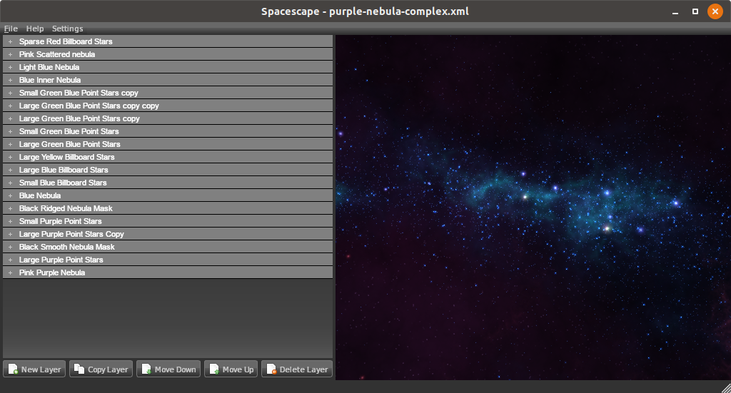
These are the default options and I’ve actually used them as the result was great.
Finally, I’ve just added some lights, a lens flare and a camera rotation in the Unity3D scene and it was done.
Play the game demo
In order to play the game (yeah I know it’s not a game, it’s just a moving 3d object on a scene), you need to load the project from the Unity3D-project/gyro-acc-test/ folder. Then you just build it by pressing Ctrl+B and this will create an executable file named teensy-wars.x86_64 and at the same time it will also launch the game. After you build the project (File » Build Settings), you can just lauch the teensy-wars.x86_64 executable.
Make sure that before you do this, you’re running the hid_manager in the background and that you’ve flashed Teensy with the teensy-motion-hid/teensy-motion-hid.ino firmware and the mpu-6050 sensor is connected properly.
Conclusions
I’m amazed with this project for many reasons. It took me 1.5 day to complete it. Now that I’m writing those lines, I’m thinking that I’ve spend more time in documenting this project and write the article rather implement it and the reason for this the power of open source, the available free software (free to use or open), the tons of available information in documents, manuals and forums and finally and most important the fact that people are willing to share their work and know-how. Of course, open source it’s not new to me, I do this for years also by myself, but I was amazed that I was able to build something like this without even use any of those tools before in such short time. Prototyping has become so easy nowadays. It’s really amazing.
Anyway, I’ve really enjoyed this project and I’ve enjoyed more the fact that I’ve realized the power that everyone has in their hands nowadays. It’s really easy to build amazing stuff, very fast and get good results. Of course, I need to mention, that this can’t replace the domain expertise in any way. But still it’s nice that engineers from other domains can jump into another unknown domain and make something quick and dirty and get some idea how things are working.
Have fun!
Comments powered by Disqus.