Into
Filters! I used to love analog filters. I mean, I still like them; but it’s being many years since I’ve designed and used any advanced passive or active analog filters. I remember spending hours of doing filter design using MathCad and plotting the Bode graphs and try to trim the frequencies. Then I was implementing those filters using mostly opamps and trimming the component values and running tests to verify the filter. Well, at that time was fun, now I’m experienced enough to know that this amount of detail in designing a simple filter is useless for the 90% of real-life cases. At least for me. Most of the times a rough estimation done on a napkin is more than enough.
Of course, there are cases that filters accuracy is critical, but not in what I’m doing anyways. Now, even just a resistor and a capacitor are just enough for filtering annoying signals or noise from a path and the accuracy for that is negligible. Nevertheless, I’ve enjoyed that era and I’ve quite missed it.
Also, back then filtering was done using analog parts and only some advanced DSP chips were started to do real-time filtering in the digital domain and other complex funky stuff. Later on the also CPUs got faster and advanced DSP was started to become a standard thing for mainstream desktop computers. Then also the MCUs got faster and real-time DSP was also possible on fast MCUs. Nowadays, you can pretty much use any MCU to implement basic filters and when it gets to ARM Cortex cores, there are even DSP CMSIS libraries that can handle the maths using even dedicated FPUs. Well, actually the STM32F303CC (aka black-pill) is one of them.
A few years back, in 2016, I was reading a book where the author was using the digital biquad filter topology to implement various of different filters and I liked this approach so much, that I’ve ported those filters to C++ code. You can find that repo here:
https://github.com/dimtass/DSP-Cpp-filters
Lately, this repo got my attention again, because I’ve seen many people starred it and did forks and I was thinking, man... I've done so many advanced stuff, but this simple weekend project got so much attention. It seems that DSP and audio is a very hot domain for many people. Although I’m a musician my self, I’m a bit old school and I don’t use any digital effects or filters, so everything on my audio path is mostly analog. Nevertheless, DSP is definitely a huge domain with a lot of interesting stuff and filtering is only a small area of this vast domain.
Therefore, I thought to port those DSP filters to C and use an ARM Cortex-M4 to test them in real time. And thus this stupid project was born.
Components
Those are the components and equipment I’ll use in this project.
STM32F303CCT6
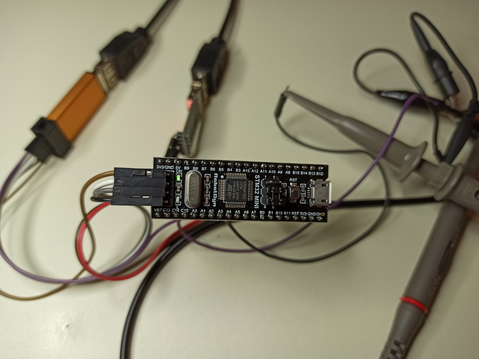
There are many black-pills out there, but I’m referring to my favorite RobotDyn STM32 mini.

This board comes with an STM32F303CCT6 running at 72MHz (also I’ve tested it overclocked at 128MHz), 256KB ROM, 40KB RAM and plenty of timers and peripherals. In this project I’ll use a timer, an ADC and a DAC, but more on that later.
SDG1025
Of course, in order to test a filter you need an input signal. I have this arbitrary signal generator for this case, but you can use any other generator you like, as long as it’s able to create signals that are in the supported range of the STM32 (0-3.3V)
Oscilloscope
You need also an oscilloscope in order to verify the signal output from the DAC. Usually, I’m using my little TDS200 for testing those stuff, but for now I’ve used my Rigol 1054z in order to capture the screenshots you’ll see in the post. Since you have an input and an output, you’ll need two channels. Because I’ll only use audio frequencies, even a basic oscilloscope is more than enough for this purpose.
Filter theory
Oh, no, no, no, I’m joking, I won’t get into this. That’s a huge domain and there are so many books, web posts and youtube videos out there that explain those things far better than I could ever explain. Therefore, in this case you need to be already familiar with what is a low-pass filter (LPF), high-pass filter (HPF), all-pass filter (APF) and band-pass filter (BPF). Well, even the names are quite self-explanatory.
Now regarding the biquad filter I can say that is a generic form of a digital IIR filter. What it actually does is that it sums products of coefficients and sample values of the input and the output. It’s just maths, but all the magic happens in the calculation of those coefficients which control the behavior of the biquad filter. Actually, those coefficients control the two poles and zeros of the filter transfer function, therefore they control the type of filter you can implement. Since biquads have two poles and two zeros, they can implement first order and second order filters.
Setup
In order to test those filters with the STM32F303 we need one ADC to sample the output signal from the generator (which is input for the STM32), then process the samples and finally convert the result sample to an analog signal using a DAC. That’s quite an easy thing to do with STM32, but what is important here is the sampling rate. Therefore, we need to sync all those states and drive the sequence using a standard sample rate. Since the STM32 is quite fast, I’ll use a sample rate of 96000 samples/sec. For audio this high fidelity as it’s 4.8x times the audio frequency range. Well, for my ears is almost 8x times as I’ve lost my upper octave in an accident during my military service, lol. Yeah, army sucks in so many different ways…
To drive the sequence with 96KHz we need a timer. So in this case, I’ll use TIM1 to trigger the ADC, then a DMA channel to copy the ADC reading as fast as possible to the RAM, then apply the filter and then pass the sample to the DAC. So this is a simple diagram of the setup.
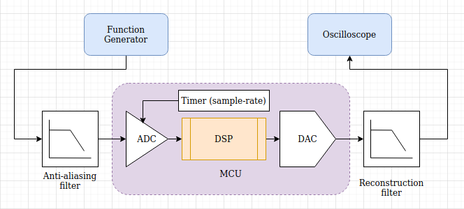
In the above diagram we see that there’s a function generator which is used to provide the input signal, in this case just a sinusoidal signal. Next there’s in an optional anti-aliasing filter, which I’m not using in my tests. In this case the anti-aliasing filter doesn’t make sense, because the SDG1025 generator outputs a clean sin, but normally you would need that in order to filter frequencies over 20KHz, so their mirror images are not shown in the 20-20KHz range that we care about.
Then it’s the MCU that uses the ADC to sample the input signal, then the DSP software algorithm (in this case the filters) and then the DAC that outputs the processed signal. Also, there’s a timer that triggers the ADC with frequency equal to the sample-rate we need. Then in the output, after the MCU, there’s an optional reconstruction filter, which again is a low pass filter that filters all frequencies above 20KHz. I’ll not use this filter on this test, because I like to see the DAC quantized signal, as I’ve also altering the sampling rate during my tests. Finally, there’s the oscilloscope that displays the output.
As you can guess, it’s expected to have a phase delay between the input and the output (ADC to DAC) as it needs time to sample, process and convert the input. From my tests this phase shift is around 25 degrees as you can see later in the screenshots, which is just a few micro-seconds.
This is the setup on my desk.
Code explanation
I’ve written a small cmake project for the stm32f303cc that implements all the above things and you can find the code here:
https://github.com/dimtass/stm32f303-adc-dsp-dac
To clone the repo locally run:
1
git clone --recursive https://github.com/dimtass/stm32f303-adc-dsp-dac.git
The supported filters in the code are:
- First order all-pass filter (fo_apf)
- First order high-pass filter (fo_hpf)
- First order low-pass filter (fo_lpf)
- First order high-shelving filter (fo_shelving_high)
- First order low-shelving filter (fo_shelving_low)
- Second order all-pass filter (so_apf)
- Second order band-pass filter (so_bpf)
- Second order band-stop filter (so_bsf)
- Second order Butterworth band-pass filter (so_butterworth_bpf)
- Second order Butterworth band-stop filter (so_butterworth_bsf)
- Second order Butterworth high-pass filter (so_butterworth_hpf)
- Second order Butterworth low-pass filter (so_butterworth_lpf)
- Second order high-pass filter (so_hpf)
- Second order Linkwitz-Riley high-pass filter (so_linkwitz_riley_hpf)
- Second order Linkwitz-Riley low-pass filter (so_linkwitz_riley_lpf)
- Second order Low-pass filter (so_lpf)
- Second order parametric/peaking boost filter with constant-Q (so_parametric_cq_boost)
- Second order parametric/peaking cut filter with constant-Q (so_parametric_cq_cut)
- Second order parametric/peaking filter with non-constant-Q (so_parametric_ncq)
All the filters are based on the standard digital biquad filter (DBF), which is displayed here:
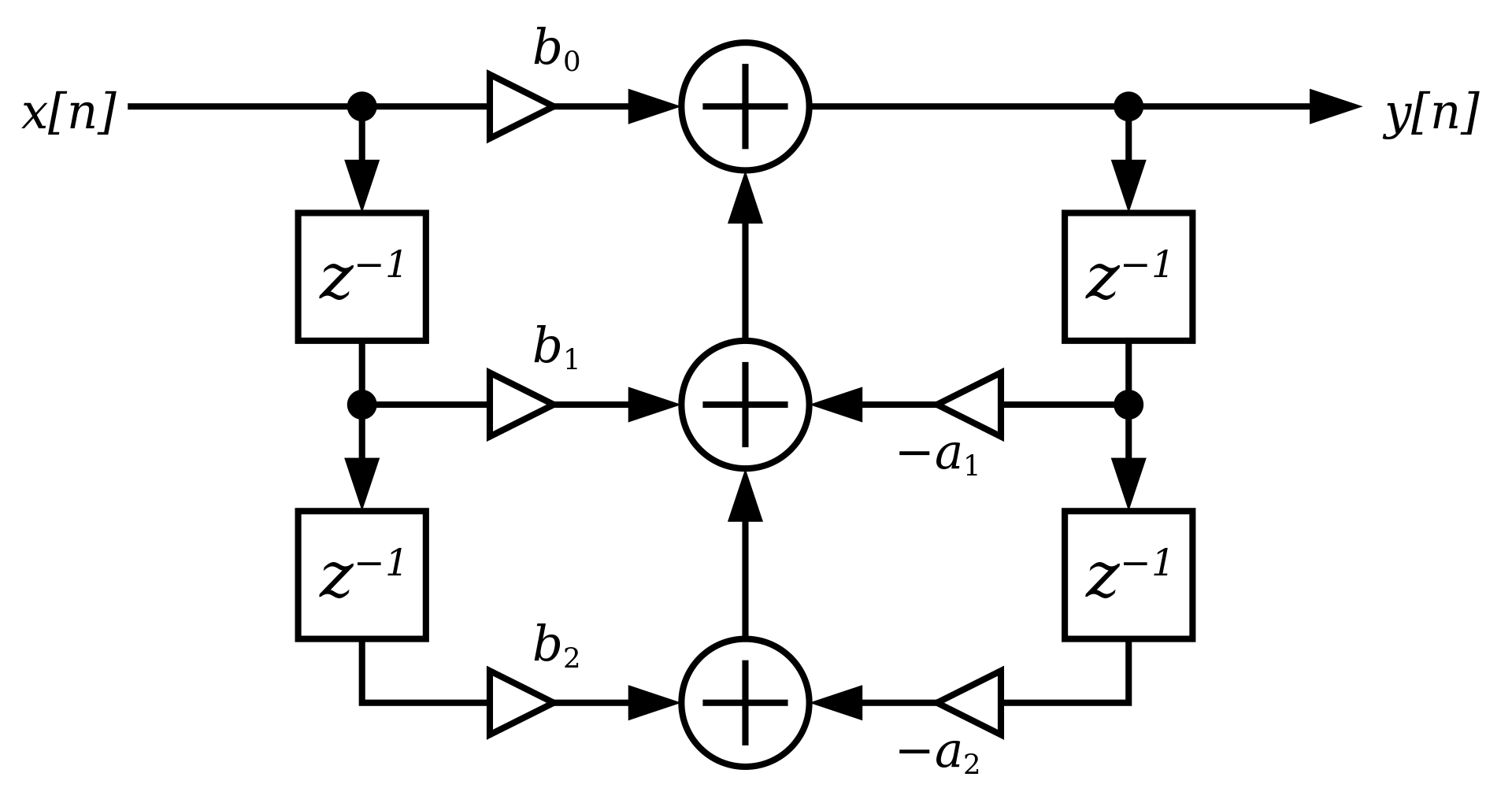
The mathematical formula for the DBF is the following:
1
y(n) = a0*x(n) + a1*x(n-1) + a2*x(n-2) - b*y(n-1) + b2*y(n-2)
Now, back to the repo you can find this code in the source/libs/filter_lib/filter_common.h as a macro. Yes, that’s right, it’s a macro. I know that many people don’t like them, but it’s fine to use macros if you know what you’re doing and it’s also DRY (Do-not-Repeat-Yourself). In my C++ code for those DSP filters for example I don’t use any macros as classes makes things much better. The macro is this one:
1
#define BIQUAD (m_coeffs.a0*xn + m_coeffs.a1*m_xnz1 + m_coeffs.a2*m_xnz2 - m_coeffs.b1*m_ynz1 - m_coeffs.b2*m_ynz2)
Well, although the README.md file in the repo is quite thorough, I’ll repeat most of the things I’ve written there also in here. I’ve added a pointer to an array of functions in order to be able to apply multiply filters on each sample. The code is in the source/main.c file and there you’ll find these lines:
1
2
#define NUM_OF_FILTERS 5
F_SIZE (*filter_p[NUM_OF_FILTERS])(F_SIZE sample);
The default array size is 5, which is more than enough, but you can increase it if you like. The reason for this is to create more complex filters by stacking other filters. For example the default filter in the repo is a band-pass (BFP) Butterworth filter composed by a high-pass filter (HPF) with corner-frequency of 5KHz and a low-pass filter (LPF) with corner-frequency of 10KHz. Therefore, the filter bandwidth is 5KHz. This is the code in main.c
1
2
3
4
5
6
/* Set your filter here: */
so_butterworth_lpf_calculate_coeffs(10000, SAMPLE_RATE);
so_butterworth_hpf_calculate_coeffs(5000, SAMPLE_RATE);
so_butterworth_hpf_set_offset(2048);
filter_p[0] = &so_butterworth_hpf_filter;
filter_p[1] = &so_butterworth_lpf_filter;
In the above code you see that first the filters are initialized by calculating the coefficients, then an offset of 2048 is added to the HPF and then I’ve added the HPF filter in the first slot of the array of filters and then the LPF in the second. The filter processing on the sample happens in the DMA interrupt.
1
2
3
4
5
6
7
8
9
10
11
12
13
14
15
16
17
18
void DMA1_Channel1_IRQHandler(void)
{
    /* Test on DMA1 Channel1 Transfer Complete interrupt */
    if(DMA_GetITStatus(DMA1_IT_TC1))
    {
        io.sample_ready = 1;
        io.dac_sample = io.adc_sample;
        for (int i=0; i<NUM_OF_FILTERS; i++) {
            if (filter_p[i])
                io.dac_sample = filter_p[i](io.dac_sample);
        }
    	DAC_SetChannel1Data(DAC1, DAC_Align_12b_R, io.dac_sample);
        irq_count++;

        /* Clear DMA1 Channel1 Half Transfer, Transfer Complete and Global interrupt pending bits */
        DMA_ClearITPendingBit(DMA1_IT_TC1);
    }
}
Also this function increments a counter (irq_count) on every interrupt and every second in the main_loop() function this counter is printed in the UART output and then it gets reset. This means that if the sampling frequency is 96000, then in your COM port terminal (I’m using CuteCom) you should see the 96000 printed every second. If not then there’s a problem somewhere in the code path or the sampling rate is too fast. You can change the sampling rate by setting the SAMPLE_RATE you want in main.c
1
#define SAMPLE_RATE 96000
The pinout for this project is in the following table:
| STM32 pin | Function |
|---|---|
| A0 | ADC in |
| A4 | DAC out |
| A9 | UART Tx |
| A10 | UART Rx |
Build and flash the code
To build the code you need to run the build script, but you need to have a GCC toolchain and cmake installed. Generally, is easier just to use Docker and build the firmware using the docker image that I’m using also in other projects and I’ve created in the DevOps for Embedded posts. To do that you only need Docker installed in your system and then run:
1
./docker-build.sh
Or if you prefer to run the full command then:
1
docker run --rm -it -v `pwd`:/tmp -w=/tmp dimtass/stm32-cde-image:0.1 -c "./build.sh"
The above command will download the image if it’s not already available and then build the code in the build-stm32/ folder. Therefore, you’ll find a bin, hex and elf file in the build-stm32/src/ folder. Then you can flash it however you like. Personally I’m using stlink on Ubuntu and an ST-Link V2. If you have the same setup, then you can use my flash script and just run
1
./flash.sh
Testing the filters
Assuming that you have a working setup now you can start playing with the filters! This gif is from the default filter in the code.
As you can see from the gif the signal starts from 1KHz and then I increase the frequency up to 20KHz. At 1KHz the output is suppressed by the HPF, after 5KHz the output is -3dB compared to input and start to increase and it reaches the same Vp-p as the input. While increasing the frequency more, the output starts to suppressed by the LPF and at 10KHz is again -3dB and it gets lower as the input increases.
Nice stuff!
Next I’ve tested various filters and they seem to working fine. I’m uploading a few pictures here for reference. For all the screenshots the sampling rate is 96KHz and the corner-frequency is 5KHz.
This is the first-order all-pass filter (APF)
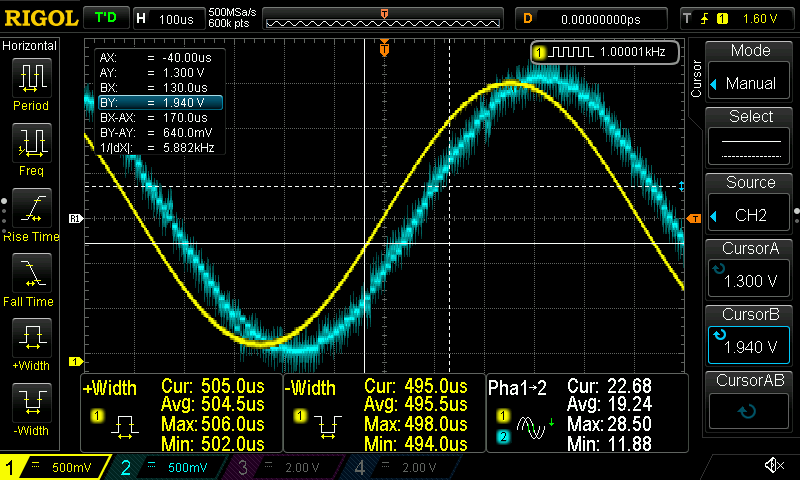
This is the first-order HPF
This is the first-order LPF
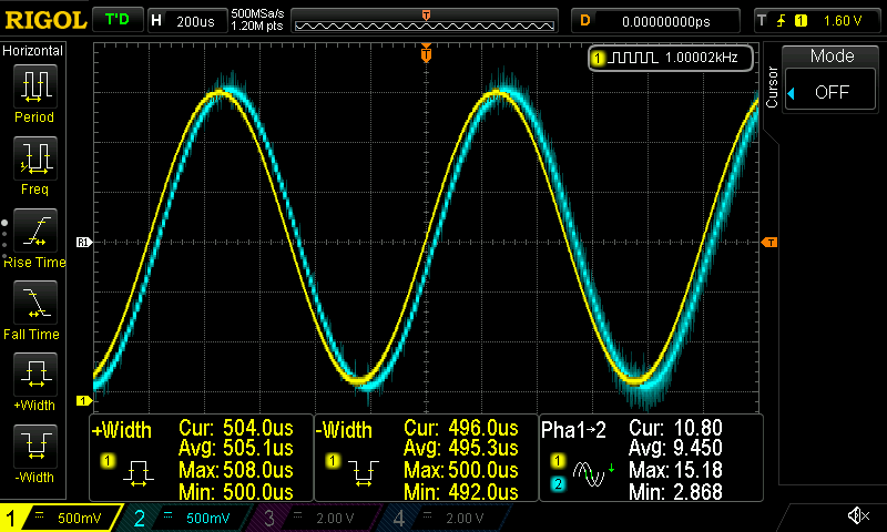
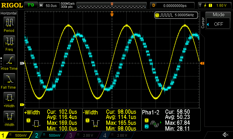
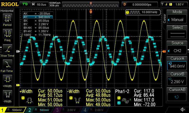
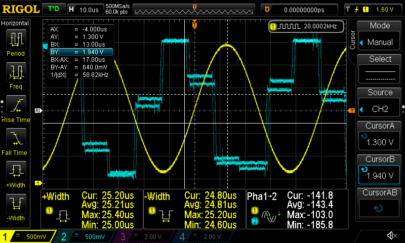
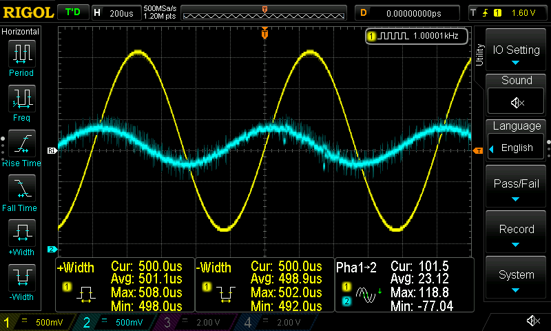
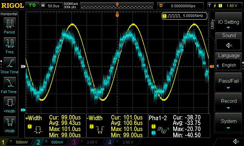
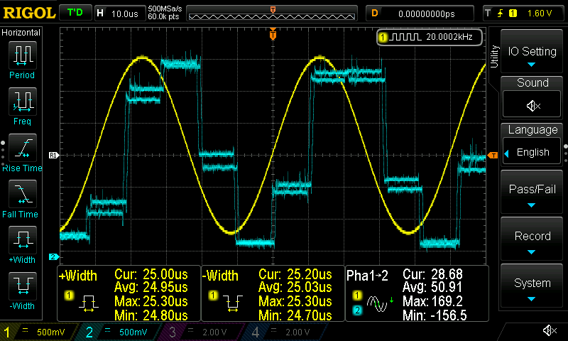
I think there’s not a real benefit uploading more screenshots. You can play around with the filters if you like and add as many filters you want to at the same time and see the result. What is interesting is the affect that the sample rate has on the DAC, therefore I’m uploading here 3 different sampling rates I’ve used (96KHz, 192KHz and 342KHz) while the input frequency is 20KHz.
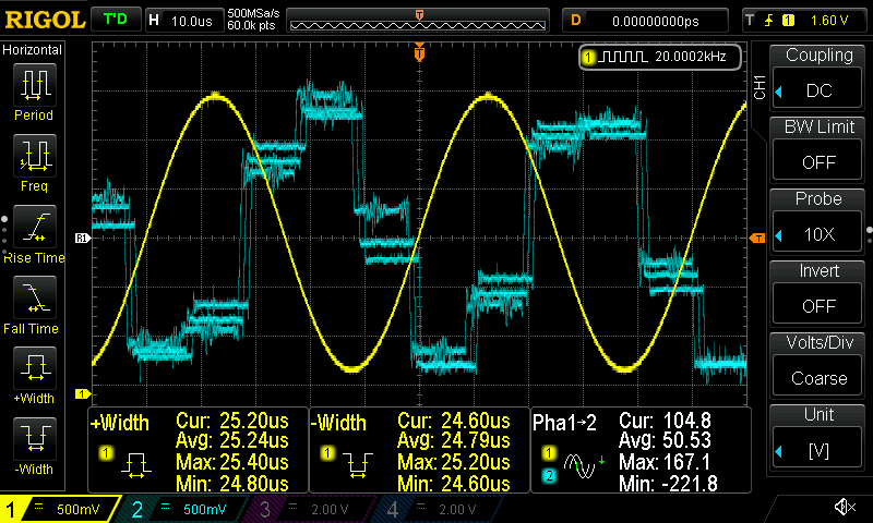
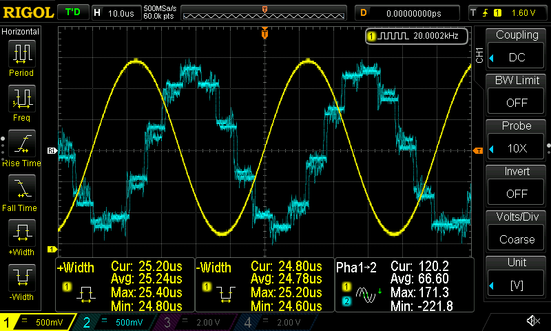
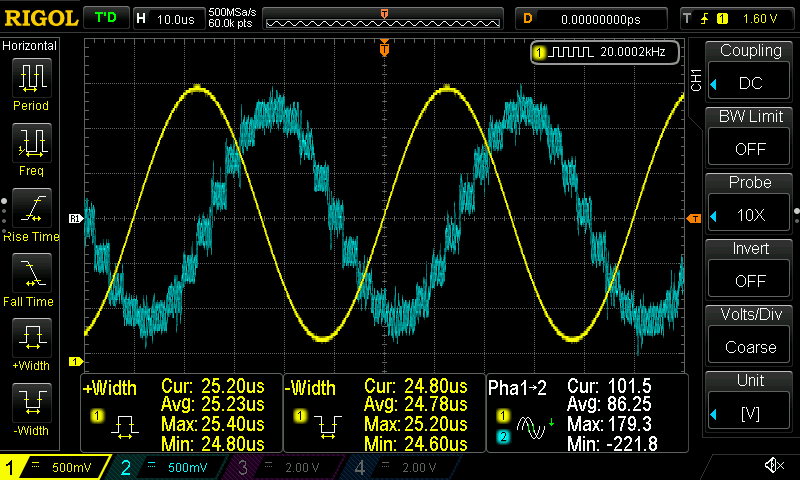
It’s obvious that as the sampling rate increases the DAC output has better resolution.
You may wonder here, why 342KHz and not 384KHz, which more common as its two times the 192KHz. Well, that’s because that’s the limit of the STM32! Actually when the core runs at the default maximum frequency (=72MHz) then the maximum sampling rate is limited at 192KHz. Therefore, I had to overclock the STM32 at 128MHz in order to achieve this 384KHz sampling rate. In order to do the same you need to build the code with an extra flag, like this:
1
docker run --rm -it -v `pwd`:/tmp -w=/tmp dimtass/stm32-cde-image:0.1 -c "USE_OVERCLOCKING=ON ./build.sh"
The USE_OVERCLOCKING=ON will enable the oveclock_stm32f303() function in the main.c. Be aware that there might be a chance that this won’t work with your MCU, but it worked in all the black-pills I have around…
Using the CMSIS-DSP library
As I’ve mentioned the STM32F303CC has a Cortex-M4 core with a dedicated FPU. This means that you can use the CMSIS-DSP library that ARM provides, for which you can find more details here. This library comes the CMSIS version of your MCU and the version that comes with the STM32F30x_DSP_StdPeriph_Lib_V1.2.3 3 is the 4.2, which is quite old, but definitely this doesn’t affect the one single function we need to use.
So, in order to test the CMSIS-DSP lib you can only use the so_butterworth_lpf filter, because I didn’t implement the process function for all filters (you’ll see why in a bit). Also you need to initialize a debug pin and use it to time the filter function. First add the dbg_pin_init() just right before you setup your filter and also setup only the so_butterworth_lpf. Your code in main() should look like this:
1
2
3
4
5
dbg_pin_init();

/* Set your filter here: */
so_butterworth_lpf_calculate_coeffs(10000, SAMPLE_RATE);
filter_p[0] = &so_butterworth_lpf_filter;
Then in the DMA1_Channel1_IRQHandler() function you need to change it like this:
1
2
3
4
5
6
7
8
9
10
11
12
13
14
15
16
17
void DMA1_Channel1_IRQHandler(void)
{
    /* Test on DMA1 Channel1 Transfer Complete interrupt */
    if(DMA_GetITStatus(DMA1_IT_TC1))
    {
        io.sample_ready = 1;
        io.dac_sample = io.adc_sample;
        DBG_PORT->ODR |= DBG_PIN;
        io.dac_sample = filter_p[0](io.dac_sample);
        DBG_PORT->ODR &= ~DBG_PIN;
    	        DAC_SetChannel1Data(DAC1, DAC_Align_12b_R, io.dac_sample);
        irq_count++;

        /* Clear DMA1 Channel1 Half Transfer, Transfer Complete and Global interrupt pending bits */
        DMA_ClearITPendingBit(DMA1_IT_TC1);
    }
}
This code will set the B7 pin high before calling the filter function and set it LOW right after, therefore you can use the oscilloscope to measure the time. Finally, in order to build the firmware using the CMSIS-DSP lib you need to build the firmware with this command:
1
docker run --rm -it -v `pwd`:/tmp -w=/tmp dimtass/stm32-cde-image:0.1 -c "USE_FPU=ON ./build.sh"
The USE_FPU flag controls the use of the CMSIS-DSP for the filter function. Finally, let’s check the filter function implementation before proceed with the benchmarks. You’ll find it in the source/libs/filters_lib/src/so_butterworth_lpf.c file.
1
2
3
4
5
6
7
8
9
10
11
12
13
14
15
16
17
F_SIZE so_butterworth_lpf_filter(F_SIZE sample)
{
    F_SIZE xn = sample;

#ifdef USE_FPU
    F_SIZE A[] = {m_coeffs.a0, m_coeffs.a1, m_coeffs.a2, -m_coeffs.b1, -m_coeffs.b2};
    F_SIZE B[] = {xn, m_xnz1, m_xnz2, m_ynz1, m_xnz2};
    F_SIZE yn = 0;
    arm_dot_prod_f32((F_SIZE*) &A, (F_SIZE*) &B, 5, &yn);
#else
    F_SIZE yn = BIQUAD;
#endif

    SAVE_FILTER_STATE;

    return(yn + m_offset);
}
When USE_FPU is defined, then I use the arm_dot_prod_f32() function to calculate the dot product of two arrays, which are the coefficients and the input/output sample values. Let’s see the results now. Please keep in mind that on those screenshots I’ve used a sampling rate of 192KHz.
First this is the result with using the CMSIS-DSP library.
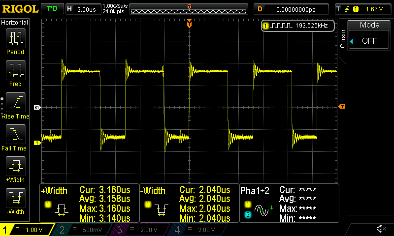
As you can see from the screenshot, the time execution of the filter function is approx. 3 microseconds. Now let’s see without using the CMSIS-DSP library:
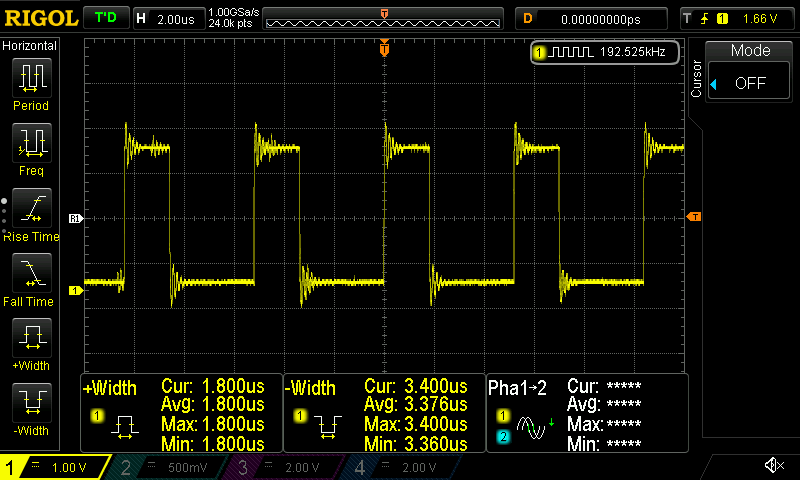
As you can see now the filtering function takes 1.7 microseconds, which is almost the half time!
So, why is that happening? Well, I didn’t check the asm, but I guess that the memory copy operations in order to create the arrays to pass to the function takes a lot of time and at the same time the compiler optimizations are good enough to make the code run fast even without the CMSIS-DSP library. You can have a look in the C flags that I’m using in cmake, but they are generally trimmed for maximum performance.
Therefore, after those initial results I decided not to continue with using the the CMSIS-DSP lib for the filter function.
Also another interesting thing is the distance of those pulses. Remember the sampling rate is 192KHz and each pulse means the call of the filter function, but there’s also other code that is running at the same time, like the sys cloc, sampling rate timer, ADC and DAC interrupts, blinking a LED e.t.c. Therefore, you can imagine how much time all those other things take. Which is too less. That’s mostly because of the DMA and the interrupts.
Anyway, it’s also interesting the sum of the high and low pulse time in the two cases. Let’s see the next table:
| Filter time (usec) | Other (usec) | Sum (usec) | |
|---|---|---|---|
| CMSIS-DSP | 3.16 | 2.01 | 5.17 |
| mathlib | 1.8 | 3.4 | 5.2 |
You see that the period between each filter function call is ~5.2 usec, therefore the frequency is 1/5.2 = 192.3KHz, which is the expected sampling rate. Therefore, it’s obvious that the MCU is near it’s limits and we can’t use faster sampling rate, but using the mathlib in this case gives us an additional 3.16-1.8= 1.36 usec to use for other tasks. Neat.
Conclusions
Well, that was a fun stupid project. So to summarize, I’ve ported my C++ filter library to C and then used an STM32F303CC to test the code and verify that the filters are working. By the way, the C port is also available in this repo as a standalone library.
There’s not much more to say really, the biquad filter seems to be working fine in all the filters versions. One thing that I need to clarify is why I had to add this 2048 offset only on the HPFs in order to works. I guess there’s something in the maths, but I’ll figure out at some point later.
Also, I’m satisfied with the ADC -> DMA -> process -> DAC speed. I can get 192KHz sampling rate at the default MCU speed and almost the double when it’s overclocked. One thing that I could do and I may do at some point in the future- is to add another ADC and DAC channel, so I can have a stereo input/output. Also the phase delay is low, just a few micro-seconds.
I didn’t expect that CMSIS-DSP would be slower than the mathlib, but after seeing the results it probably should be expected as the memcpy in order to create the needed arrays for the arm_dot_prod_f32() take quite much time.
To be honest, I don’t really see many real usage scenarios for such filters as it’s very easy to implement them with passive components outside the MCU easily. Where it could be really useful though, is when you need an adaptive or programmable filter. In this case, you can use this project and add UART commands to control the type of the filter, the corner frequency, Q and BW and the sampling rate in real-time. This would be awesome and very easy to do using this project as a template. Maybe I can do this in the future, but it’s a bit boring procedure for me for now and my time is a bit limited.
Just by estimating from the current results, I believe 192KHz stereo is not possible at the default 72MHz, but 96KHz should be OK.
Also if you plan to really use this, then you’ll probably need the reconstruction filter after the DAC to remove the quantization noise. A second-order LPF with 20KHz cut-off frequency would be fine. I would probably use an active filter with an opamp so I can also have output buffering and drive higher loads. Well, that depends on your case, but either way any 2nd order LPF would be fine.
I hope you enjoyed this little project.
Have fun!
Comments powered by Disqus.