Intro
Welcome to another completely stupid project!
This time I’ll show you how to implement a sine generator using a dirt cheap stm32f407 board. It really doesn’t make any sense to just build a sine generator, especially that way and using an STM32 processor, but it’s fun and at some point later I’ll post a project with the making of a more useful DDS (direct digital synthesizer). As usual let’s see the components and their prices.
Components
STM32F407ZET6 / STM32407VET6 development board
You can find cheap development boards for both stm32f407vet6 and stm32f407zet6 micro-processors on e-bay for $11 and $15. The vet6 is a bit cheaper compared to zet6. Their only difference is the package and therefore the number of available GPIOs. In more detail the vet6 has 100 pins (LQFP100 package) and 82 GPIOs and the zet6 has 144 pins (LQFP144 package) and 114 GPIOS and both have 512KB flash and 192KB ram. If you think that the additional 32 GPIOs worth paying $4 more then go for it, or if you’re like me and hate dilemmas buy both and be happy. Therefore, search e-bay for stm32f407vet6 or stm32f407zet6 and buy the cheapest ones. This is how stm32f407vet6 looks like
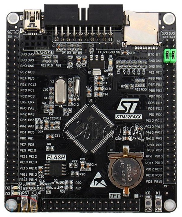
For the record there is a difference in the layout between vet6 and zet6 boards. The vet6 has the SD card on the top right side and the usb connector on the top left side and the zet6 has these components mirrored. Also, this post is written in 2017 so if you read this in 2030 then expect to find those boards in a museum.
USB to UART module
Most of the time when you develop on micro-controller you need a debug uart port. This project is no different, therefore you’ll need this.
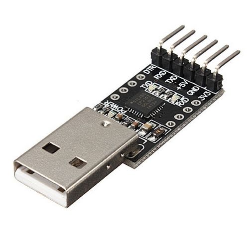
This you can find in Ebay for $1.2.
J-Link
I’ve used J-Link to flash the board during development as the board has a jtag connector, but you may use an st-link or even a cheap usb programmer with an SWD interface. Use whatever you have that can flash this thing.
Passive components
You’re going to need a few passive components to implement a low-pass filter (LPF) for the internal stm32 DAC. Nothing fancy, just a resistor R=1300Ω and a capacitor C=5.9nF. More details about the LPF later. Also the cost for these is unknown, they are so cheap that probably cost around $0.something.
PCM5102A
Finally if you want to play around with a real DAC then buy one of these cheap pcm5102a boards on e-bay for $7.
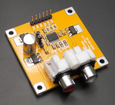
This board has everything you need to drive the pcm5102 DAC using the stm32’s I2S interface and also you get a bonus stereo RCA connector that you can connect to your speakers.
Good to have
Well, you’re going to build a sine generator, so it’s good to have an oscilloscope. Also you may need a breadboard or a prototype breadboard to implement the LPF.
Making the stupid project
Using the internal DACs
Ok, now that you have everything you need let’s see how you build a sine generator. First, I’ll show how you can use the stm32’s internal DACs, so grab the board and clone the following git repo.
https://bitbucket.org/dimtass/stm32f407_dds_dac
Depending on your OS (Windows or Linux) follow the instructions in the README. What you actually need is a bare metal arm compiler, cmake and then run the build script. After that you’ll find the binary file in build-stm32 folder. Flash this bin on the stm32 board and reset the board. If you feel adventurous spend some time to read the crap source code. Everything is done using double buffering DMAs and FIFO buffers for faster speed and because of that the sampling rate in dds_defs.h is set to 384KHz. Be aware that if you don’t use this specific board then your board might have a different xtal crystal, which means that you need to edit the HSE_VALUE in stm32f4xx.h
In the internal_dac.c file you’ll find the code for the two internal DACs and in dds.c the code for the sine generator. The sine generator code is quite interesting as it uses the phase accumulator concept, which is very clever and nice to know. The idea is that you have an accumulator that you increment with a phase that is analogous with the frequency of the desired sine output. Yeah, I know, bοring, but if you are interested in the concept have a look at those links (link, link, link, link).
Connect the USB to UART module to the USART1 the following way:
| USB pin | STM32 pin |
|---|---|
| TX | PA9 |
| RX | PA10 |
| GND | GND |
Also, connect your oscilloscope to PA4 to probe the DAC1 channel and PA5 to probe the DAC2 channel.
Now, use a terminal (I’m using Br@y’s Terminal) and open the COM port using 115200, 8 data bit, no parity, 1 stop bit and no handshake. Also make sure that the received CR bytes are handled as CR+LF (CR=LF option in Brays terminal). You can change the sine frequency with the following command:
1
FREQ=<channel>,<frequency>
where:
channelis 1: for DAC1, 2: for DAC2frequencyis the desired frequency in Hz
For example:
1
FREQ=1,5434.25
sets the DAC1 frequency to 5434.25 Hz
1
FREQ=2,18934.32
sets the DAC2 frequency to 18934.32 Hz`
That way you can have two individual DAC channels with two different frequencies. Regarding the code implementation, there are several ways to implement this DAC functionality on the STM32. You can individually control each DAC using its data holding register or use the dual data holding register, use dual timers with dual DMAs or single timer dual DMAs or single timer with single DMA (in case of using the dual data holding register). I’ve choose to use single timer, dual DMA, single data holding register because it makes the output sine waveform simpler, but I would like to implement also the single timer, single DMA, dual data holding register because it may be even faster as fewer IRQs are triggered.
Edit: Now you can git clone the single timer, single DMA, dual data holding register repo from here if you want to do any performance tests.
Next is the output of a single DAC channel in various frequencies, without using an LPF filter in the output.


The displayed frequencies are 0.1, 100, 1000, 10000, 20000, 48000 and 192000 Hz. As expected the quantization noise is high as no anti-aliasing filter is used in the output. The following images are after using a simple analog first order LPF anti-aliasing filter.


The difference is that now there’s much lower quantization noise in higher frequencies (e.g. 48KHz) but also the output amplitude is getting smaller after aprox. 20KHz as the filter cut-off frequency is 20750.32Hz (R=1300Ω, C=5.9nF). There’s no point to display the 192KHz output as the amplitude is almost zero.
Using an external DAC (PCM5102)
It’s nice having fun with the internal DACs on the STM32 but… let’s use real DAC that can handle 16, 24 and 32 bit stereo channel audio. These days you can find good DACs really cheap. Texas (TI) has some nice chips that are sold as PCB boards on e-bay. For this test I’m using a PCM5102 board. I’ve also got some cirrus logic cs4344 DACs I would like to play with, but unfortunately I haven’t managed to find a board for them, which means I have to build mine at some point. The only cs4344 boards you can find on ebay are some USB DACs, but they don’t fit the purpose and also they are using the old out-of-life PCM2702.
Anyway, what’s the main difference between the internal DAC and this PCM5102? Well, the first one is internal! That means that there everything is happen in the STM32, no external components, no protocol interfaces, nothing. This means increased speed but less performance as the internal DAC is a basic 12-bit DAC. On the other hand now, by using an external DAC you get better performance as the chip is dedicated and engineered for the purpose, but this also mean that you need an interface to drive the DAC. In this case the I2S interface is used and it’s set to 16/48 (16-bit & 48KHz). Well, 16/48 it’s more than enough for my old rusted ears and it’s fine for testing. Maybe at some point I can try if STM32 can go up to 32/192 which is the highest that the STM32’s I2S can get (the PCM5102 supports up to 32/384).
Note: The
PCM5102board has its own regulators; therefore, even though the VCC is rated at 3V3 (same asSTM32F407) you’ll need an external power supply 5~9V, because if you apply 3V3 it won’t even start.
Download the source code from the following repo and read the README.md file how to build the binaries:
https://bitbucket.org/dimtass/stm32f407_dds_i2s_dma
Connect the board the following way:
| PCM5102 pin | pin |
|---|---|
| BCK | STM32 PC10 |
| DATA | STM32 PC12 |
| LRCK | STM32 PA15 |
| GND | STM32 GND |
| GND | PSU GND |
| VCC | PSU 5V |
Set the FMT jumber LJ instead of I2S (LJ stands for Left Justified)
The I2S on the STM32 has DMA, double buffering and FIFO enabled for better performance. In case you use a different board then you should refer to the stm32 reference manual to set the correct N and R values on the RCC_PLLI2SConfig() function in i2s_dma.c. Actually, I would advice you to do that always as the I2S rate is very sensitive to the XTAL frequency and therefore even small variations on the XTAL speed wil have an affect on the output I2S rate. For more info check the table 127 in 28.4.4 in the reference manual which are the correct values, but I suggest that you use an oscilloscope to trim the N value as the on-board crystal sucks. Using the oscilloscope try to find the correct value that gives more precise frequencies for the LRCK (I2S clock). E.g. in my case to get 16/48 the table suggests to use PLLI2SN=192 (that’s N) and PLLI2SR=5 (that’s R), but by using these values the LRCK clock was quite off, so I had to set the PLLI2SN=200 to get the correct bitrate. The correct clock frequency/bitrate for a stereo 16/48 I2S audio is 216Fs, where Fs=48KHz in this case, so bitrate=1536000Hz.
If you want to have a look at the code then you’ll find all the I2S code in the i2s.h and i2s_dma.c files and the phase accumulator algorithm for the sine in dds.h/dds.c. To change the output frequency for the L and R channel then use a terminal as before and use the following commands.
1
FREQ=<channel>,<frequency>
where:
channelis L: for Left, R: for Right audio channelfrequencyis the desired frequency in Hz
For example:
1
FREQ=L,5434.25
sets the Left channel frequency to 5434.25 Hz, and
1
FREQ=R,18934.32
sets the Right channel frequency to 18934.32 Hz
So, like before you have two individual channels to play with. Next are some oscilloscope captions on various frequencies (0.1, 100, 1000, 20000 and 22000Hz).


You’ll see that the output anti-aliasing filtering is much better now, compared the example with the DACs. In this case is not possible to get frequencies higher than 22KHz.
Conclusion
That was another meaningless stupid project. I mean really, you can’t do anything useful with these stuff, but you can experiment and use pieces to implement other more useful projects like a DDS that can output different waveforms or even a synthesizer. It’s also quite rare to find code for the STM32 even in the internet that uses DMAs with double buffering and FIFOs for both DAC and I2S, so keep the code for reference.
Have fun!