Driving an ILI9341 LCD with an overclocked stm32f103 (updated)
Intro
LCDs… I think LEDs and LCDs are probably the most common wet dream of people who like playing with embedded. I mean, who doesn’t like blinking LEDs and furthermore who doesn’t like to draw graphics with a microcontroller on an LCD? If you don’t press Alt+F4 now please.
LEDs are easy. Toggling a pin or flashing a LED is the first breath of every project. There you know that your microcontroller’s heart is beating properly and it doesn’t have arrhythmia. Then, driving a character LCD is a bit more harder, but still easy; but driving a graphic LCD is definitely more harder, especially if you’re starting from the scratch. Do you have to start from the scratch, though? Nah… There are many projects out there and also this is another one.
OK, so what’s the motivation behind this, if there are so many projects out there? For me it was the fact that I don’t like to use all these arduino-like stuff with my STMs, I don’t like HAL and I couldn’t find a proper cmake project that builds out of the box, without special dependencies like specific IDEs, compilers e.t.c. With this project you just download cmake and a gcc compiler, point the cmake toolchain to your gcc compiler and run build. Then it works… (maybe)
Of course, if you are regular customer here, there’s no need to say that this is a completely stupid project. It does nothing. No, really. You won’t see any fancy graphics that other people post with their STMs in youtube. You’ll see just a yellow screen. Why? Because I just wanted to benchmark and have a template to use for any other project.
Note: I’ve updated the code and post, because I’ve added support for the
xpt2046/ads7843touch controller. I’ve usedSPI2withDMAto read the touch sensor and also I’m using thePENIRQinterrupt pin and not polling.
Overclocking, SPI, DMA and other fancy buzzwords
If you found this by searching on the web, then you’re probably here because you know exactly what you want. SPI & DMA!!1! The reason that I like bluepill stm32 boards is that the have a lot of DMA channels and they are dirt-cheap. On top of that you can overclock it up to 128MHz!
So, why DMA is important? Well, I won’t bother you with the details here, if you need to know more than it’s much much faster, then you need to do some web-searching for the specific details, as there are people that already explain these stuff better than me. The fact is that by using DMA on SPI’s tx/rx the transfer speed sky-rockets and you can achieve the maximum available bandwidth.
On the other hand, overclocking is more interesting. The stm32f103 can be easily overclocked by just changing the PLL value. Then you can increase the main clock from 72MHz to 128MHz. Not bad, right? Especially if you think that a project which drives a graphic LCD will benefit a lot from this speed increase. I assume that you’re not crazy enough to do that on a commercial project, but if you do then you’re my hero.
In this project I’ve done some benchmarking with two different system clocks @72MHz and @128MHz and there’s a significant difference as you see later in the benchmarks.
Components
STM32
I’m using an stm32f103c8t6 board (bluepill). These modules cost less than €2 in ebay and you may have already seen me using them also in other stupid projects.

ILI9341
There is a very standard LCD module that you find in ebay and it costs around $7. It’s 2.8” TFT, supports 240x320 resolution, it has a touch interface and an sd card holder. The part name is TJCTM24028-SPI and is the following one:
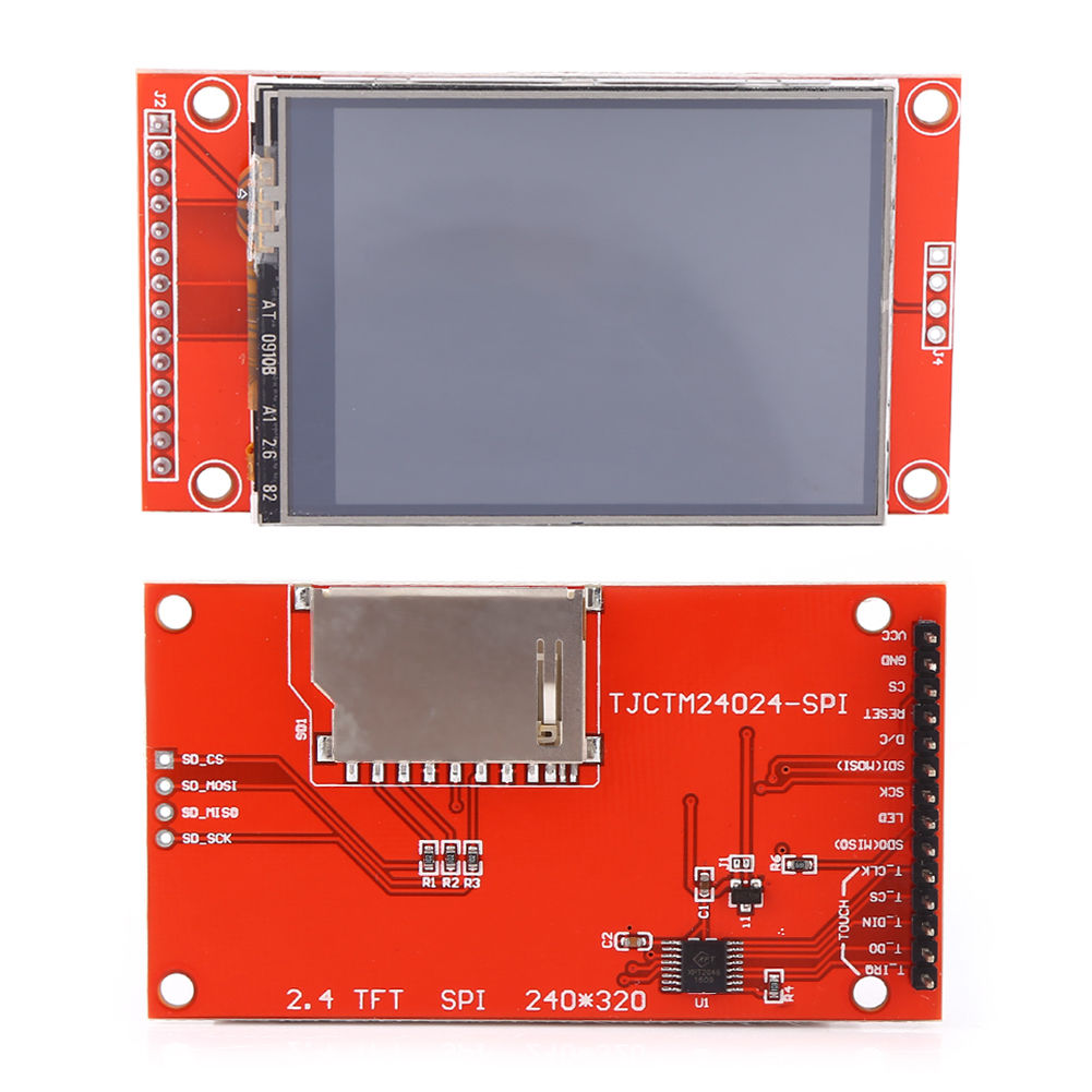
It’s a beauty, right?
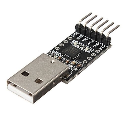
USB-uart module
You need this to print the FPS count every second and also if you want to add your custom commands. You can find these on ebay with less than€1.50 and it looks like that
ST-Link
Finally, you need an ST-Link programmer to upload the firmware, like this one:
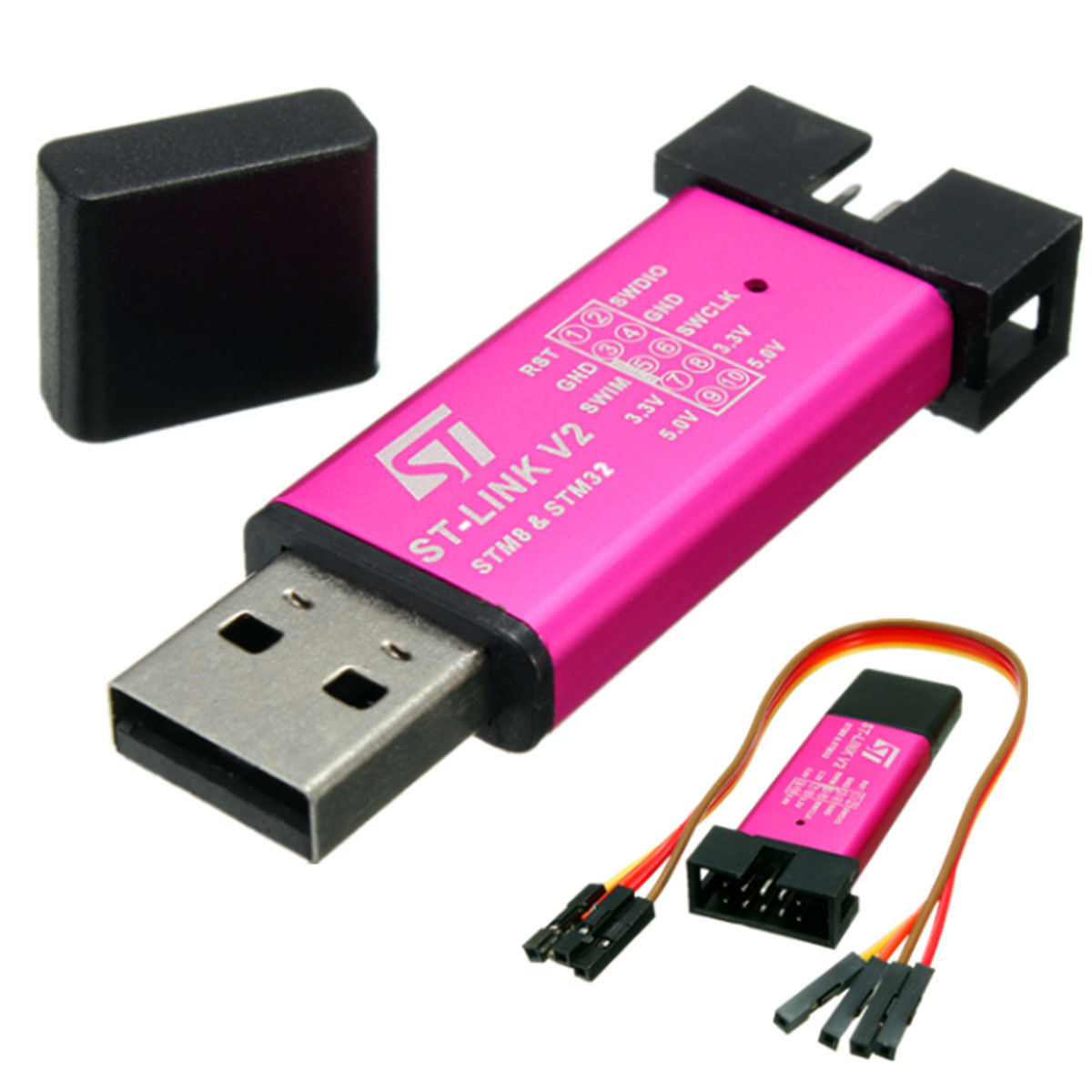
Or whatever programmer you like to use.
Pinout connections
As the LCD is not wireless you need to connect it somehow to your stm32. We’re lucky in this case, because both LCD and the stm32 have conductive pins that if they’re connected with each other in the proper way then it may work. The connections you need to do are:
| STM32 | ILI9341 (LCD) |
|---|---|
| PA0 | LED |
| PA2 | RESET |
| PA3 | D/C |
| PA4 | CS |
| PA5 | SCK |
| PA6 | SDO(MISO) |
| PA7 | SDI(MOSI) |
| 3.3 | VCC |
| GND | GND |
| STM32 | ILI9341 (touch conrtoller) |
|---|---|
| PB8 | T_IRQ |
| PB14 | T_DO |
| PB15 | T_DIN |
| PB12 | T_CS |
| PB13 | T_CLK |
| STM32 | UART module |
|---|---|
| PA9 (TX) | RX |
| PA10 (RX) | TX |
| GND | GND |
You can power the stm32 from the USB connector.
Project source code
You can download the project source code from here:
https://github.com/dimtass/stm32f103-ili9341-dma/
All you need to do is install (or have already installed) a gcc toolchain for ARM. I’m using the gcc-arm-none-eabi-7-2017-q4-major, that you can find here. Just scroll down a bit, because there are newer toolchains; but from the tests I’ve done here, it seems this produces the most compact code. Then depending your OS, change the path of the toolchain in the TOOLCHAIN_DIR variable in the project’s file cmake/TOOLCHAIN_arm_none_eabi_cortex_m3.cmake. Last, run ./build.shon Linux or build.cmdon Windows to build and then flash the bin/hex on the stm32.
Results
The SPI speed of the stm32f103 by using DMA can achieve an SPI clock up to 36MHz when the mcu is running on the default highest frequency which is 76MHz. That’s really fast already compared to other Cortex-M3 mcus with the same frequency (even faster mcus). To use the default 72MHz clock you need to comment out line 47 in main.c here, otherwise the clock will set to 128MHz.
This is a capture of CLK/MOSI when sending the byte 0xAA.

With the above clock settings, the stm32f103 achieves 29 FPS when drawing all the pixels of the screen.
By overclocking the mcu to 128MHz the SPI/DMA speed is much higher. To enable the oveclocking you need to un-comment line 47 here (SystemCoreClock = overclock_stm32f103();), which by default is already enabled.
This is a capture of CLK/MOSI when sending the byte 0xAA.

Now you can see that the SPI clock frequency is now ~63MHz, which is almost the double as the previous. That means that the updating of all the pixels on the screen can be done in a rate of 52 fps, which is quite amazing for this €2 board.
Touch controller (UPDATE)
I’ve lost my sleep knowing that I didn’t implemented the touch control interface, therefore I’ve updated the code and added support for the touch controller and also a calibration routine.
So, now there are two function modes. The first one (and default) is the benchmark mode and the other mode is the calibration. During the calibration mode you can calibrate the sensor and you need to do that if you want to retrieve pixel x/y values. Without calibration you’ll only get the adc sensor values, which may or may not be what you want.
To enter the calibration mode you need to send a command to the uart port. The supported commands are the following:
1
MODE=<MODE>
where:
BENCH: Benchmark modeCALIB: Calibration mode
1
FPS=<MODE>
where:
0: Disable FPS display1: Tx FPS on UART2: Tx FPS on UART and on display
1
TOUCH=<MODE>
where:
0: Do not Tx X/Y from touch to UART1: Tx X/Y from touch to UART
The default values are MODE=BENCH, FPS=0, TOUCH=0. Therefore to enter to the calibration mode send this command to the UART: MODE=CALIB.
The calibration routine is very simple, so do not expect fancy handling in there. Even the switch statement in ili9341_touch_calib_start() is not needed as it’s a completely serial process. I was about to implement a state machine, but it didn’t worth it, but I left the switch in there.
So, when you enable the calibration mode, you’ll get this screen.
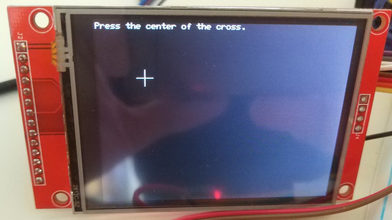
Then you need to press the center of the cross. Behind the scenes, this code is in the ili9341_touch_calib.c file, inside the ili9341_touch_calib_start() function, which at the state STATE_DRAW_P1 draws the screen and then waits in STATE_WAIT_FOR_P1 for the user to press the cross. I’ve added bouncing control in thexpt2046_polling() function, but generally the xpt2046 library doesn’t have. So the xpt2046_update() function which updates the static X/Y variables of the lib doesn’t have de-bouncing. The reason for this is that this provides a generic solution and some times de-bouncing is not always wanted, so if it does it can be implemented easily.
Anyway after pressing the point on the screen then other 2 points will be appear and after that the code will calculate the calibration data. The calibration is needed if you want to get the touch presses expressed in pixels that correspond to the screen pixels. Otherwise, the touch sensor only returns 12-bit ADC values, which are not very useful if you need to retrieve the pixel location. Therefore, by calibrating the touch sensor surface to the LCD, you can get the corresponding pixels of the pixels that are just under the pressure point.
The algorithm for that is in the touch_calib.c file and it actually derives from an application note from TI which is called Calibration in touch-screen systems and you can probably find it in this link. The only thing worth a note is that there are two main methods for calibration which are the 3 and 5-point. Most of the times you find the 5-point calibration method, but also the 3-point gives a good result. There a calc file in the sources source/libs/xpt2046-touch/calculations.ods that you can use to emulate the algorithm results. In this file the (X’1,Y’1), (X’2,Y’2), (X’3,Y’3) are the points that you read from the sensor (12-bit ADC values) and (X1,Y1), (X2,Y2), (X3,Y3) are the pixels in the center of each cross you draw on the screen. Therefore, in the ods file I’ve just implemented the algorithms of the pdf file. The same algorithms are in the code.
After you finish with the calibration, the calibration data are printed out in the serial port and also are stored in the RAM and they are used for the touch presses. After a reset those settings are gone. If you want to print the ADC and pixel values (after the calibration) on the serial port then you can send the TOUCH=1 command on the UART. After that every touch will display both values.
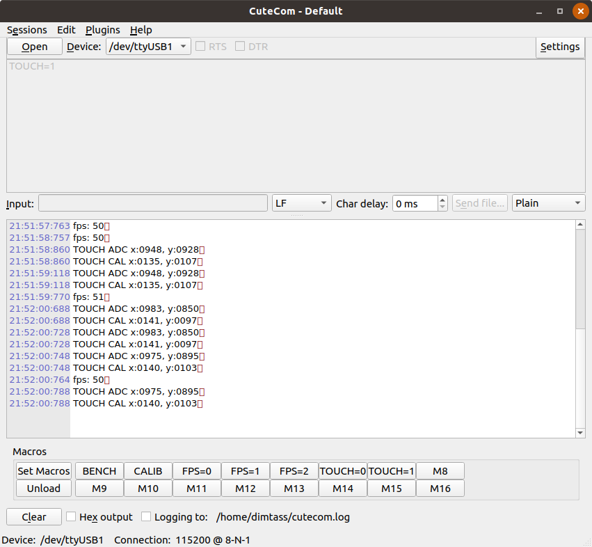
Finally, if you enable to show the FPS on the LCD you will see something weird.
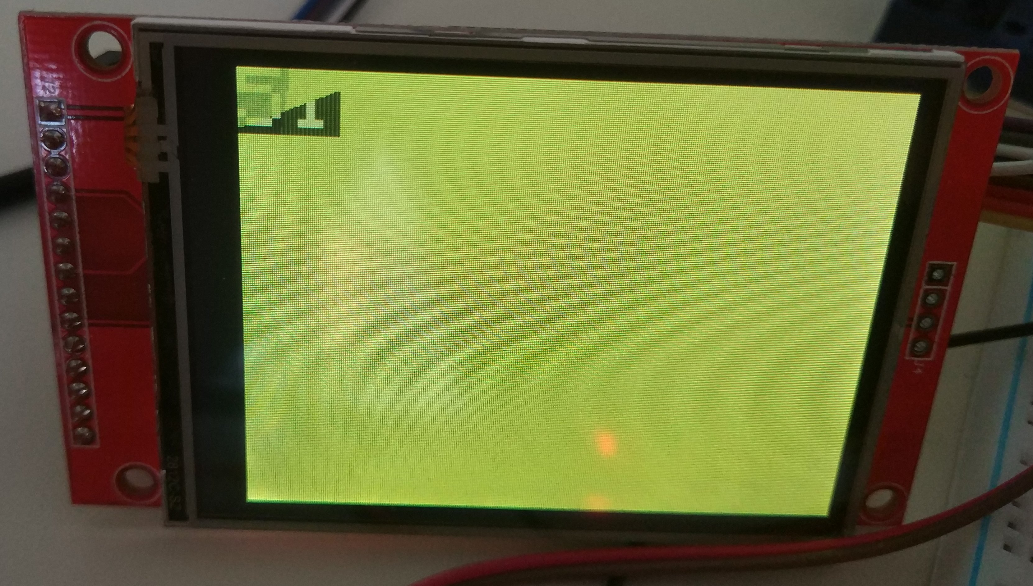
This displays the FPS rate of drawing all the pixels on the screen and you see a tearing in the number, which is 51. This happens because the number print overwriting that part of the screen when is displayed and also it gets overwritten from the full display draw. The reason for that is to simplify the process and also do not insert more delay while doing the maths.
Generally, I think the code is straight forward and it serves just a template for someone to start writing his code.
Conclusion
stm32f103, rocks. That’s the conclusion. Of course, getting there is not as easy as using an arduino or a teensy board, but the result pays off the difficulty of getting there. And also when you get there is not difficult anymore.
Again, this is a really stupid and completely useless project. You won’t see any fancy graphics with this code, but nevertheless is a very nice template to create your own graphics by using an optimized SPI/DMA code for the stm32f103 and also with the overclocking included. That’s a good deal.
Of course, I didn’t wrote the whole code from the scratch, I’ve ported some code from herewhich is a port from the Adafruit library from the arduino. So it’s a port of a port. FOSS is a beautiful thing, right?
Have fun!
Comments powered by Disqus.