Linux and the I2C and SPI interfaces (part 2)
Intro
Note: because I had to recover the db and there wasn’t a backup of this post, the images are only thumbnails and the comments were lost 🙁
In the previous stupid project I’ve implemented a very simple I2C and SPI device with an Arduino that was interfaced with a raspberry pi and there I’ve done some tests by using various ways to communicate with the Arduino. There I’ve pretty much showed that for those two buses it doesn’t really matter if you write a kernel driver or you just use the user space to access the devices. Well, if you think about it, spidev is also a kernel driver and also when you access the I2C from the user-space there’s still a kernel driver that does the work. So writing a driver for a specific subsystem instead of just interface them with a custom user-space tool has its uses, but it’s also not necessary and needs some consideration before you decide to go to either way.
Still, there was something interesting missing from that stupid project. What about speed and performance? What are your options? How these options affect the general performance? Is there a magic solution for all the cases? Well, with this stupid project I will try to fail to answer those questions and make it even more worse to give any valuable information and answers to these questions.
Components
NANOPI NEO
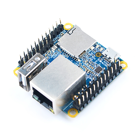
For the last stupid project I’ve used a raspberry pi, but I’ve also provided the sources for you to use also the nanopi neo. This time I won’t be that kind so I’ll only use the nanopi neo. The reason is that I like its small format and it’s quite capable for the task and also I didn’t want to use a powerful board for this. So, it’s a low-mid tier board and also dirty cheap.
STM32F103
Last time I’ve used the Arduino nano. Well, nano it’s an excellent board to implement an I2C/SPI slave device in… minutes. But, it lacks performance. So, it’s completely incapable to stress out the nanopi neo. Therefore, we need something much faster and here comes the STM32F103 as it has all the good stuff in there. 72MHz (or up to 128MHz if you overclock it, which I did, of course), DMA for both the I2C and SPI and also very, very, very cheap (I’m talking about the famous blue-pill). Therefore, I’ve implemented an I2C and SPI slave that both use DMA for fast data transfers.

OTHER COMPONENTS
The rest of the components are exactly the same with the previous stupid project. So we have a whatever photo-resistor (it doesn’t really matter) and a whatever LED.
Project
This stupid project is focused actually on the Linux kernel. As everyone learns now in school the kernel comes in two main flavors, the SMP and PREEMPT-RT kernel. The first in the normal mainline kernel and the second one is the real-time patched version of the mainline. I won’t get into the details, but just to simplify, the main difference is that the PREEMPT-RT kernel, actually guarantees that any process that runs in the CPU will get a fair and predictable time of execution, which minimizes the latency of the application. Oversimplified, but that’s not a post about the Linux kernel.
Therefore, what happens if you have a couple of fast devices that you want to interface under various conditions, like the CPU has a low or heavy background load? To find this out we actually need a fast slave, therefore the stm32f103 is just right for that, as we’ve seen in this stupid project that the SPI can achieve up to 63MHz by using DMA, which is way faster that the Arduino nano (and probably even the nanopi neo actually). So, by assuring that the slave device won’t be our bottleneck were good to go. Here you’ll find the repo for the project:
https://github.com/dimtass/linux-stm32-spi-i2c
In order to build the nanopi neo image for both SMP and RT kernel you need Yocto, but again I won’t get into the details on that (you can read the README.md file in the repo for more detailed info). Therefore, to switch between the SMP and RT kernel you need to use either of the following combinations in the build/conf/local.conf file:
1
2
PREFERRED_PROVIDER_virtual/kernel = "linux-stable"
PREFERRED_VERSION_linux-stable = "4.19%"
Or for the PREEMPT-RT:
1
2
PREFERRED_PROVIDER_virtual/kernel = "linux-stable-rt"
PREFERRED_VERSION_linux-stable-rt = "4.19%"
Also you should build the arduino-test-image like the previous project (it’s the same image actually).
So, now let’s go to some fancy stuff. In the repo there is a tool in the linux-app folder. You need to build this with the Yocto SDK or any other arm toolchain. This tool actually opens the i2c and spi devices and reads/writes data from them in a loop according to the options you’re passing in the command.
To make it a bit different, compared to the previous project, this time the SPI slave is the photo-resistor ADC and the I2C slave is the PWM LED (it was the opposite in the previous). Anyway, that doesn’t really matters, you can change that in the source code of the stm32f103 which is also available in the repo and you need also to build that and flash it on the mcu. Pretty much if you read the previous README file, it’s quite the same thing.
Benchmarks
I’ve performed the benchmarks with the stm32f103 running on 72MHz and 128MHz, too; but there wasn’t any difference at all really, as I’ve limited the SPI bandwidth to 30MHz. The reason for that was actually the cabling that causing a lot of errors above that frequency and it seems that the problem was the nanopi neo and not the stm32f103. Still, the results are interesting and I was able to get valuable information.
I’ve performed various tests. First with two different kernels, SMP and PREEMPT-RT. Then for each kernel I’ve tested a range of SPI frequencies (50KHz, 1MHz, 2MHz, 5MHz, 10MHz, 20MHZ, 30MHz). The provided tool does that automatically, actually. Then for all the above cases I’ve tested the kernel with no load, then with a light load and then with heavy load. The light load was, guess what? printf of course. Well, printf might sound silly, but in a while loop does the trick because the uart buffer fills up pretty quickly and then the kernel will have to flush the buffer and send the data. For the heavy load I’ve just used the Linux stress tool. I’ve also included a calc file in the repo with my results.
So let’s get to the fun stuff. No. Before that I want also to say that there were two kind of benchmarks the first was a pin on the stm32f103 which was toggling every time a full read/write cycle was performed. That means that the Linux app was reading the ADC value of the photoresistor from the stm32f013, then it was writing that value to the I2C PWM LED on the stm32f103. Every time this cycle was performed a pin from the stm32f103 is toggling state. Therefore by measuring the time of a single pulse you actually get the time of the cycle.
Before proceed these are the kernel versions for the SMP and PREEMPT-RT kernels:
1
Linux nanopi-neo 4.19.91-allwinner #1 SMP ... 15:26:48 UTC 2019 armv7l GNU/Linux
1
Linux nanopi-neo 4.19.82-rt30-allwinner #1 SMP PREEMPT RT ... 20:12:29 UTC 2019 armv7l GNU/Linux
SMP KERNEL
Let’s see the first three images. These are some oscilloscope probings with the SMP kernel and the SPI frequency at 500KHz, which is a very low frequency.


The first image is a zoom in on the stm32f103’s toggle pin. As I’ve said two toggles (or a pulse if you prefer) is a full read/write cycle, which means that in this time a 16-bit word on the SPI and a 3-bytes on the I2C are transferred. Because the I2C is much slower (100KHz) it has a strong affect on the speed compared to the SPI, but we try to emulate a real-life scenario here. In this case, the average cycle time is 475 μsecs (you see that the average is calculated for both low and high pulse).
The second and third screenshot display the toggle pin output when we’re running the light load with the printf. Wow! What’s going there? You see there are large gaps between the read/write cycles. Why? Well, that’s because of printf and the UART interface. UART is the dinosaur of the comm peripherals and its sloooow. In this case has only a 115200 bps baudrate. And why there are gaps, you’ll think. There are gaps because the printf is inside a while loop, which means that it fills the kernel UART buffer very fast and at some point the kernel needs to flush this buffer in order to create more space for the next bytes. During the flush is occupied with the UART peripheral which doesn’t support DMA in this case and there you have it… Huge gaps where the kernel flushes the UART buffer. We can extract valuable information from this, though. The middle picture shows that the kernel spends 328 ms to empty the UART buffer (see the BX-AX value on the top left corner). During this time you a gap. Then in the last picture you see that for the next 504 ms performs read/writes on the I2C/SPI. This behavior is with the default kernel affinity and scheduler priority per process.
Now let’s see the same output when the SPI is set to 30MHz which for the current setup seems to be the maximum frequency without getting errors.


In the first picture we see now that a full SPI/I2C read/write cycle takes 335 μsecs which is much faster compared to the 500KHz SPI speed. You can also see that the printf time is 550 ms and the SPI/I2C read/write time 218 ms, which means that the kernel uses the CPU for almost the same amount of time to empty the printf buffer, but also the SPI/I2C transactions are using the CPU for almost the half time. That seems that the kernel CPU time is tied to the SPI/I2C statistics.
Now let’s use the user-space tool to get some different numbers. In this case I’ll run the benchmark mode of the tool which counts the SPI/I2C read/write cycles per second. Each second is an iteration. Therefore, the tool also takes a parameter for how many iterations it will run. For example the following command, means that the tool will use /dev/i2c-0 and /dev/spidev-0 in benchmark mode (-m 1) and 20 iterations/runs/seconds (-r 20) and with the printf (light load) disabled (-p 0).
1
./linux-app -i /dev/i2c-0 -s /dev/spidev0.0 -m 1 -r 20 -p 0
After this test runs it will print some result, for example:
1
2
3
4
5
6
7
8
9
10
11
12
13
14
15
16
17
18
19
20
21
22
23
24
25
26
27
28
29
30
31
32
33
34
35
36
37
38
39
40
41
42
43
44
45
46
47
48
49
50
51
52
53
54
55
56
57
58
59
60
61
62
63
64
65
66
67
68
69
70
71
72
73
74
75
76
77
78
79
80
81
82
83
84
85
86
87
88
89
90
91
92
93
94
95
96
97
98
99
100
101
102
103
104
105
106
107
108
109
110
111
112
113
114
115
116
117
118
119
120
121
122
123
124
125
126
SPI speed: 1000000 Hz (1000 KHz)
2249
2235
2243
2264
2256
2250
2246
2248
2250
2237
2231
2246
2241
2237
2253
2262
2260
2261
2261
2264
        SPI speed: 2000000 Hz (2000 KHz)
2257
2261
2253
2246
2261
2265
2259
2254
2251
2246
2241
2229
2261
2270
2269
2250
2244
2258
2263
2246
        SPI speed: 5000000 Hz (5000 KHz)
2269
2253
2281
2278
2284
2287
2277
2270
2263
2273
2256
2273
2266
2270
2285
2292
2272
2268
2276
2280
        SPI speed: 10000000 Hz (10000 KHz)
2272
2268
2275
2263
2278
2283
2295
2273
2269
2274
2280
2280
2274
2291
2265
2286
2294
2310
2290
2309
        SPI speed: 20000000 Hz (20000 KHz)
2291
2291
2317
2266
2294
2291
2306
2260
2289
2305
2285
2286
2298
2281
2288
2294
2278
2250
2298
2270
        SPI speed: 30000000 Hz (30000 KHz)
2307
2301
2271
2296
2304
2312
2292
2296
2301
2278
2296
2317
2309
2305
2282
2315
2290
2272
2305
2308
There you see that for each SPI speed the number of SPI/I2C read/write cycles are counted and printed. I won’t paste other data here, but I’ll use only the average values instead. You can have a look to the second sheet spreadsheet in the calc ods file for all the data.
So let’s see the average values when we use the benchmark mode, for 20 runs and the printf on and off.
| SMP | -m 1 -r 20 -p 0 | -m 1 -r 20 -p 1 |
|---|---|---|
| 1MHz | 2750.75 | 1561.55 |
| 2MHz | 2843.75 | 1499.45 |
| 5MHz | 2938.78 | 1427.05 |
| 10MHz | 2936.2 | 1450.65 |
| 20MHz | 2987 | 1902.6 |
| 30MHz | 2986.6 | 1902.65 |
From the above table I make the following conclusions, there are almost twice as much SPI/I2C read/write cycles with the printf enabled in the loop and when using the SMP kernel. Wow, nobody expected that… And that when there no printf then after the 5MHz there’s no much difference in the number of cycles, but there is difference when the printf is enabled especially after the 20MHz. Anyway, as expected the faster the clock the more cycle counts.
But let’s now also enable a quite heavy load in the background and re-run those tests to see what happens. The full command I’ve used for the stress tools is:
1
stress --cpu 4 --io 4 --vm 2 --vm-bytes 128M
The above command means that the stress tool will utilize 4 cores, spawns 4 worker threads and two extra threads that spinning a malloc/free of 128MB each to utilize memory load. And these are the averages:
| SMP | -m 1 -r 20 -p 0 | -m 1 -r 20 -p 1 |
|---|---|---|
| 1MHz | 1733.7 | 1155.5 |
| 2MHz | 1874.95 | 1186.9 |
| 5MHz | 1760.65 | 1196.9 |
| 10MHz | 1731.4 | 1154.65 |
| 20MHz | 1698.7 | 1170.2 |
| 30MHz | 1826.7 | 1298.75 |
Now with the background heave load we see of course a huge drop in the performance for the SMP kernel, for both cases with either the printf on or off. Here the frequency doesn’t really have a great impact, but it still performs better. Any increase in the performance that is more that the statistic error is welcome. Therefore even those 100-200 full read/write cycles are a better performance, it just doesn’t scale uniform as the previous example that there wasn’t a background load.
Now let’s see the PREEMPT-RT kernel…
PREEMPT-RT KERNEL
Let’s have a look to a couple of oscilloscope probings like we did in case of the SMT kernel.


In this case the average time for a full SPI/I2C cycle is 476 μsec. You can also see that the kernel performs read/write cycles for 504 ms and also spends 324 ms to flush the UART buffer. I will make the conclusions about how the SMP and the PREEMPT-RT are compared in the next section, so I’m continuing with the rest of the benchmarks.
These are the two tables for the P kernel with the benchmark result as the previous example.
| PREEMPT-RT | -m 1 -r 20 -p 0 | -m 1 -r 20 -p 1 |
|---|---|---|
| 1MHz | 2249.7 | 1448.55 |
| 2MHz | 2254.2 | 1444.65 |
| 5MHz | 2273.89 | 1447.55 |
| 10MHz | 2281.45 | 1457.95 |
| 20MHz | 2286.9 | 1457.55 |
| 30MHz | 2297.85 | 1458.7 |
So, this means that the light load that printf adds to the CPU has a huge affect on the performance, although the kernel is the real-time kernel. That’s expected though, because real-time doesn’t mean that you’ll get the performance from each process that you get it’s running as the only process in the CPU, it just means that the scheduler will be fair and the process is guaranteed to get a minimum amount of time to execute frequently. Therefore, the whole performance is affected from any additional load as in the case of the SMP.
Now let’s see what’s happening when there’s a heavy background load as before. So I’ve used the exact same parameters for the stress tool as before and these are the results I’ve got.
| PREEMPT-RT | -m 1 -r 20 -p 0 | -m 1 -r 20 -p 1 |
|---|---|---|
| 1MHz | 1815.15 | 1398.7 |
| 2MHz | 1930.25 | 1443.35 |
| 5MHz | 1963.55 | 1399.9 |
| 10MHz | 1929.9 | 1441.5 |
| 20MHz | 2045.65 | 1472 |
| 30MHz | 2002.05 | 1442.65 |
So, what we see here? Wow, right? There’s really no big difference compared to the previous table. It seems that although the load now is much higher, the performance impact was quite low. Why’s that? Well, that’s what the RT kernel does, it makes sure that your process will get a fair time to run and it will preempt other processes frequently, so there’s no process that will occupy the CPU more time that the others. Again, the printf has a great impact, because the problem relies in the implementation and there’s no DMA to unload the CPU from the task of sending bytes over the UART.
Results
So let’s compare the results that we have from the two kernels and see what we got. I’ll create two new tables with the sum of the results for the light and heavy load. This is the table without the heavy background load.
| SMP | RT | SMP+pr | RT+pr | |
| 1MHz | 2750.75 | 2249.7 | 1561.55 | 1448.55 |
| 2MHz | 2843.75 | 2254.2 | 1499.45 | 1444.65 |
| 5MHz | 2938.79 | 2273.89 | 1427.05 | 1447.55 |
| 10MHz | 2939.2 | 2281.45 | 1450.65 | 1457.95 |
| 20MHz | 2987 | 2286.9 | 1902.6 | 1457.55 |
| 30MHz | 2986.6 | 2297.85 | 1902.65 | 1458.7 |
In this table we see that without any load, the SMP kernel is much faster compared to RT. That’s happening because the scheduler is not really fair, but gives as much as processing time to the SPI/I2C and the benchmark tool as the rest of the processes are idle. Quite the same happens for the RT without the load, but still the CPU is forced to switch between also other tasks and processes that don’t have much to do, so the scheduler is more “fair”.
On the next two columns, the impact of the printf in the while loop has a huge affect on both kernels. Nevertheless, the SMP kernel gives more processing time to the benchmark tool and the SPI/I2C interfaces, therefore the SMP has approx. 450 more read/write cycles more in higher frequencies.
nother thing is obvious from the table is that the SPI/I2C read/writes scale with the frequency increment and the RT kernel is not. So for the RT kernel it doesn’t matter if the SPI bus is running on 1MHz or 30MHz. Cool, right? So that means that if you’re running on a RT kernel you don’t have to worry in optimizing your SPI to achieve the max frequency, because it doesn’t make any difference. But on the SMP you should definitely do any optimizations.
So in this case, it seems that the SMP kernel is much, much better for such use scenarios. What are those scenarios? Well, SPI displays are definitely one of those, for example. And this most probably is the same for every other peripheral that demands a high throughput (e.g. pcie, USB, e.t.c.)
Now let’s go to the next table that the benchmark is running with a heavy load in the background.
| SMP | RT | SMP+pr | RT+pr | |
| 1MHz | 1733.7 | 1815.15 | 1155.5 | 1398.7 |
| 2MHz | 1874.95 | 1930.25 | 1186.9 | 1443.35 |
| 5MHz | 1760.65 | 1963.55 | 1196.9 | 1399.9 |
| 10MHz | 1731.4 | 1929.9 | 1154.65 | 1441.5 |
| 20MHz | 1698.7 | 2045.65 | 1170.2 | 1472 |
| 30MHz | 1826.7 | 2002.05 | 1298.75 | 1441.65 |
Wait, what? What happened here? In all benchmarks the RT kernel not only scores higher, but also if you see the full table in the calc file, you’ll see that there is smooth and consistent performance between each SPI/I2C read/write cycle for the RT kernel. The SMP kernel from the other hand, has a great variation between the cycles and also the average performance is lower. The performance difference between the SMP and RT is not huge, but its substantial. Who doesn’t want 100,200 or even 300 more SPI/I2C read/write cycles per second, right?
So what happened here? Well, as I’ve mentioned before, the RT scheduler is fair. Therefore, for the RT kernel you get the almost the same performance as you get with a lower load, because the kernel will more or less assign the CPU for the same amount of time. But, the performance on the SMP is getting a great impact, because now the kernel needs to assign more time to other processes that may need the kernel for more time. Hence, this difference between the last two tables.
OK, so what’s better then? What should I use? Which is better? Well… that depends. What are your needs? What your device is doing? For example, if you want to drive an SPI display with the max framerate possible then forget about RT, but on the same time make sure that there’s no other processes in your system that load the CPU that much, because then your framerate will drop even more compared to the RT kernel. Then why use the RT kernel? You would use the RT kernel if your system needs to perform specific tasks in a predictable way, even under heavy load. An example of that for example is audio or let’s say that you drive motors and you need minimum latency under every circumstance (no load, mid load, high load). In most cases the SMP kernel is what you need when a lot of IOs and a high throughput is needed and also almost every other case, except when you need low latency and predictable execution.
Another thing needs notice here is that the RT kernel is not just a plug n play thing that you boot in you OS and everything works just as fine as with SMP. Instead, there may a lot of underlying issues and bugs in there, that may have an undefined behaviour which is not triggered with the SMP kernel. This means that some drivers, subsystems, modules or interfaces, even a hardware may don’t be stable with the RT kernel. Of course, the same goes for the SMP, but at least the SMP is used much more widely and those issues are come to the surface and fixed sooner, compared to the RT kernel. Also, if your kernel is not a mainline kernel then it’s a hard and long process to convert it to a fully PREEMPT-RT kernel, as the patches for the RT kernel are targeting the mainline kernel only. So until all the PREEMP-RT patches become mainline and also we get to the point that your hardware supports those mainline versions, might take a looong time.
This post is just a stupid project and is not meant to be an extensive review, benchmark or versus between the SMP and the PREEMPT-RT. Don’t forget where you are. This is a stupid projects blog. And for that reason let’s see the SPI protoresistor and I2C PWM LED in action.
Have fun!
Comments powered by Disqus.