Intro
This is the first part, you can read the second part here.
Most of the people that reading that blog, except that they don’t have anything more interesting to do, are probably more familiar with the lower embedded stuff. I like the baremetal embedded stuff. Everything is simple, straight-forward, you work with registers and close to the hardware and you avoid all the bloatware between the hardware and the more complicated software layers, like an RTOS. Also, the code is faster, more efficient and you have the full control of everything. When you write a firmware, you’re the God.
And then an RTOS comes and says, well, I’m the god and I may give you some resources and time to spend with my CPU to run your pity firmware or buggy code. Then you become a semi-god, at best. So Linux is one of those annoying RTOSes that demotes you to a simple peasant and allows you to use only a part of the resources and only when it decides to. On the other hand, though, it gives you back a lot more benefits, like supporting multiple architectures and have an API for both the kernel and the user-space that you can re-use among those different architectures and hardware.
So, in this stupid project we’ll see how we can use a couple of hardware interfaces like I2C and SPI to establish a communication between the kernel and an external hardware. This will unveil the differences between those two worlds and you’ll see how those interfaces can be used in Linux in different ways and if one of those ways are better than the other.
Just a note here: I’ve tested this project in two different boards, on a raspberry pi 3 model B+ and on a nano-pi neo. Using the rpi is easier for most of the people, but I prefer the nano-pi neo as it’s smaller and much cheaper and it has everything you need. Therefore, in this post I will explain (not very thorough) how to make it work on the rpi, but in the README.md file in the project repo, you’ll find how to use Yocto to build a custom image for the nano-pi and do the same thing. In case of the nano-pi you can also use a distro like armbian and build the modules by using the sources of the armbian build. There are so many ways to do this, so I’ll only focus one way here.
Components
Nanopi-neo
I tried to keep everything simple and cheap. For the Linux OS I’ve chosen to use the nanopi-neo board. This board costs around ~$12 and it has an Allwinner H3 cpu @800 or @1200MHz and a 512MB RAM. It also has various other interfaces, but we only care about the I2C and the SPI. This is the board:
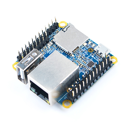
You can see the full specs and pinout description here. You will find the guide how to use the nano-pi neo in the repo README.md file here:
https://github.com/dimtass/linux-arduino-spi-i2c
Raspberry pi
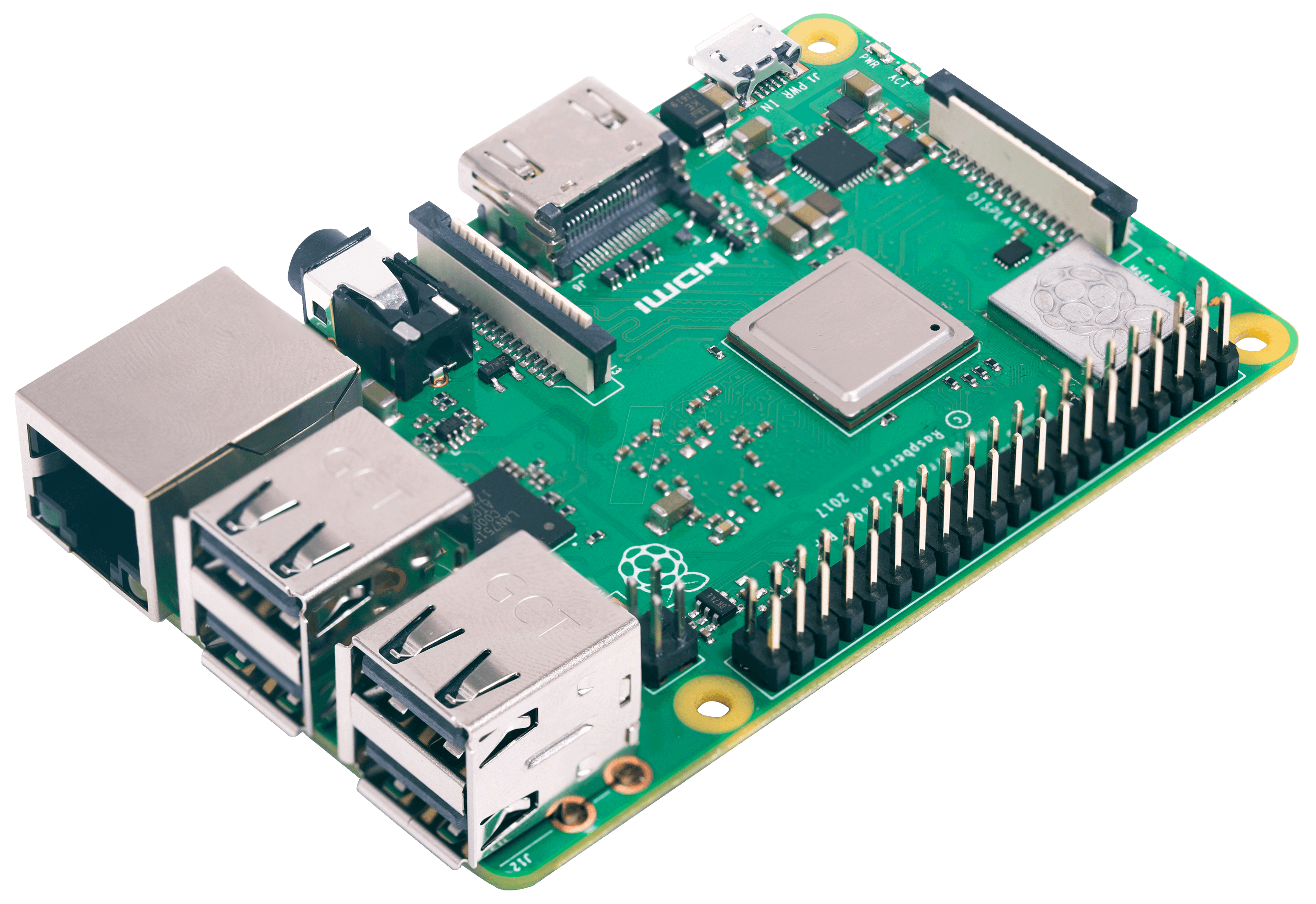
I have several raspberry pi flying around here, but in this case I’ll use the latest Raspberry Pi 3 Model B+. That way I can justify to my self that I bought it for a reason and feel a bit better. In this guide I will explain how to make this stupid project with the rpi, as most of the people have access to this rather to a nano pi.
Arduino nano
Next piece of hardware is the arduino-nano. Why arduino? Well, it’s fast and easy, that’s why. I think the arduino is both bless and curse. If you have worked a lot with the baremetal stuff, arduino is like miracle. You just write a few line of codes and everything works. On the other hand, it’s also a trap. If you write a lot of code in there, you end up losing the reality of the baremetal and you become more and more lazy and forget about the real hardware. Anyway, because there’s no much time now, the Arduino API will do just fine! This is the Arduino nano:

Other stuff
You will also need a photoresistor, a LED and a couple of resistors. I’ll explain why in the next section. The photoresistor I’m using is a pre-historic component I’ve found in my inventory and the part name is VT33A603/2, but you can use whatever you have, it doesn’t really matter. Also, I’m using an orange led with a forward voltage of around 2.4V @ 70mA.
Project
OK, that’s fine. But what’s the stupid project this time? I’ve though the most stupid thing you can build and would be a nice addition to my series of stupid projects. Let’s take a photo-resistor and the Arduino mini and use an ADC to read the resistance and then use the I2C interface as a slave to send the raw resistance value. This value actually the amount of the light energy that the resistor senses and therefore if you have the datasheets you can convert this raw resistance to a something more meaningful like lumens or whatever. But we don’t really care about this, we only care about the raw value, which will be something between 0 and 1023, as the avr mega328p (arduino nano) has a 10-bit ADC. Beautiful.
So, what we do with this photo-resistor? Well, we also use a PWM channel from the Arduino nano and we will drive a LED! The duty cycle of the PWM will control the LED brightness and we feed the mega328p with that value by using the SPI bus, so the Arduino will be also an SPI slave. The SPI word length will be 16-bit and from those only the 10-bit will be effective (same length as the ADC).
Yes, you’ve guessed right. From the Linux OS, we will read the raw photo-resistor value using the I2C interface and then feed back this value to the PWM LED using the SPI interface. Therefore, the LED will be brighter when we have more light in less bright in dark conditions. It’s like the auto-brightness of your mobile phone’s screen? Stupid right? Useless, but let’s see how to do that.
Connections
First you need to connect the photo-resistor and the LED to the Arduino nano as it’s shown in the next schematic.
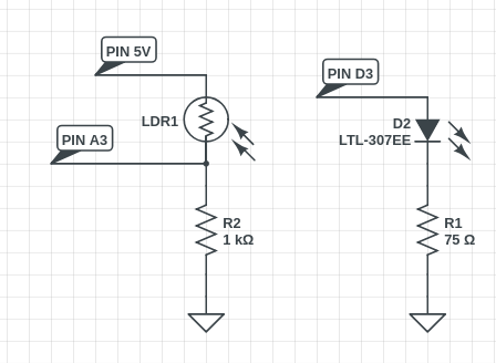
As you can see the D3 pin of the Arduino nano will be the PWM output that drives the LED and the A3 pin is the ADC input. In my case I’ve used a 75Ω resistor to drive the LED to increase the brightness range, but you might have to use a higher value. It’s better to use a LED that can handle a current near the maximum current output of the Arduino nano. The same goes for the resistor that creates a voltage divider with the photo-resistor; use a value that is correct for your components.
Next you need to connect the I2C and SPI pins between the Arduino and the rpi (or nanopi-neo). Have in mind that the nano-pi neo has an rpi compatible pinout, so it’s the same pins. These are the connections:/
| Signal | Arduino | RPI (and nano-pi neo) |
|---|---|---|
| /SS | D10 | 24 (SPI0_CS) |
| MOSI | D11 | 19 (SPI0_MISO) |
| MISO | D12 | 21 (SPI0_MOSI) |
| SCK | D13 | 23 (SPI0_CLK) |
| SDA | A4 | 3 (I2C0_SDA) |
| SCL | A5 | 5 (I2C0_SCL) |
You will need to use two pull-up resistors for the SDA and SCL. I’ve used 10ΚΩ resistors, but you may have to check with an oscilloscope to choose the proper values.
Firmwares
You need to flash the Arduino with the proper firmware and also boot up the nanopi-neo with a proper Linux distribution. For the second thing you have two option that I’ll explain later. So, clone this repo from here:
https://github.com/dimtass/linux-arduino-spi-i2c
There you will find the Arduino sketch in the arduino-i2c-spi folder. Use the Arduino IDE to build and to upload the firmware.
For the rpi download the standard raspbian strech lite image from here and flash an SD card with it. Don’t use the desktop image, because you won’t need any gui for this guide and also the lite image is faster. After you flash the image and boot the board there are a few debug tweaks you can do, like remove the root password and allow root passwordless connections. Yeah, I know it’s against the safety guidelines, don’t do this at your home and blah blah, but who cares? You don’t suppose to run your NAS with your dirty secrets on this thing, it’s only for testing this stupid project.
To remove the root password run this:
1
passwd -d root
Then just for fun also edit your /etc/passwd file and remove the x from the root:x:... line. Then edit your /etc/ssh/sshd_config and edit it so the following lines are like that:
1
2
3
4
5
PermitRootLogin yes
#PubkeyAuthentication yes
PasswordAuthentication yes
PermitEmptyPasswords yes
UsePAM no
Now you should be able to ssh easily to the board like this:
1
ssh root@192.168.0.33
Anyway, just flash the arduino firmware and the raspbian distro and then do all the proper connections and boot up everything.
Usage
Here’s the interesting part. How can you retrieve and send data from the nanopi-neo to the Arduino board? Of course, by using the I2C and the SPI, but how can you use those things inside Linux. Well, there are many ways and we’ll see a few of them.
Before you boot the raspbian image on the rpi3, you need to edit the /boot/config.txt and add this in the end of the file, in order to enable the uart console.
1
enable_uart=1
Raw access from user space using bash
Bash is cool (or any other shell). You can use it to read and write raw data from almost any hardware interface. From the github repo, have a look in the bash-spidev-example.sh. That’s a simple bash script that is able to read data from the I2C and then send data to the SPI using the spidev module. To do that the only thing you need to take care of is to load the spidev overlay and install the spi-tools. The problem with the debian stretch repos is that the spi-tools is not in the available packages, so you need to either build it yourself. To do this, just login as root and run the following commands on the armbian shell:
1
2
3
4
5
6
7
8
9
10
apt-get install -y git
apt-get install -y autotools-dev
apt-get install -y dh-autoreconf
apt-get install -y i2c-tools
git clone https://github.com/cpb-/spi-tools.git
cd spi-tools
autoreconf -fim
./configure
make
make install
Now that you have all the needed tools installed you need to enable the i2c0 and the spidev modules on the raspberry pi. To do that add this run the raspi-config tool and then browse to the Interfacing options and enable both I2C and SPI and then reboot. After that you will be able to see that there are these devices:
1
2
/dev/spidev0.0
/dev/i2c-1
This means that you can use one of the bash scripts I’ve provided with the repo to read the photo-resistor value and also send a pwm value to the LED. First you need to copy the scripts from you workstation to the rpi, using scp (I assume that the IP is 192.168.0.36).
1
2
cd bash-scripts
scp *.sh root@192.168.0.36
Before you run the script you need to properly set up the SPI interface, using the spi-config tool that you installed earlier, otherwise the default speed is too high. To get the current SPI settings run this command:
1
pi-config -d /dev/spidev0.0 -q
If you don’t get the following then you need to configure the SPI.
1
/dev/spidev0.0: mode=0, lsb=0, bits=8, speed=10000000, spiready=0
To configure the SPI, run these commands:
1
2
spi-config -d /dev/spidev0.0 -m 0 -l 0 -b 8 -s 1000000
./bash-spidev-example.sh
With the first command you configure the SPI in order to be consistent with the Arduino SPI bus configuration. Then you run the script. If you see the script then the sleep function is sleep for 0.05 secs, or 50ms. We do that for benchmark. Therefore, I’ve used the oscilloscope to see the time difference every SPI packet and the average is around 66ms (screenshots later on), instead of 50. Of course that includes the time to read from the I2C and also send to the SPI. Also, I’ve seen a few I2C failures with the following error:
1
2
3
4
5
mPTHD: 0x036e
mError: Read failed
PTHD: 0x
n\PTHD: 0x036d
xPTHD: 0x036e
Anyway, we’ve seen that way that we are able to read from the I2C and write to the SPI, without the need to write any custom drivers. Instead we used the spidev module which is available to the mainline kernel and also a couple of user-space tools. Cool!
Using a custom user-space utility in C
Now we’re going to write a small C utility that opens the /dev/i2c-1 and the /dev/spidev0.0 devices and read/writes to them like they are files. To do that you need to compile a small tool. You can do that on the rpi, but we’ll need to build some kernel modules later so let’s use a toolchain to do that.
The toolchain I’ve use is the gcc-linaro-7.2.1-2017.11-x86_64_arm-linux-gnueabihf and you can download it from here. You may seen that this is a 32-bit toolchain. Yep, although rpi is a 64-bit cpu, raspbian by default is 32-bit. Then just extract it to a folder (this folder in my case is /opt/toolchains) and then you can cross-build the tool to your desktop with these commands:
1
2
3
export CC=/opt/toolchains/gcc-linaro-7.2.1-2017.11-x86_64_arm-linux-gnueabihf/bin/arm-linux-gnueabihf-gcc
${CC} -o linux-app linux-app.c
scp linux-app root@192.168.0.36:/root
Then on the rpi terminal run this:
1
./linux-app /dev/i2c-1 /dev/spidev0.0
Again in the code I’ve used a sleep of 50ms and this time the oscilloscope shows that the average time between SPI packets is ~50ms (screenshots later on), which is a lot faster compared to the bash script. In the picture you see the average is 83, but that’s because sometimes there are some delays because of the OS like 200+ms, but that’s quite expected in a non PREEMPT-RT kernel. Also, I’ve noticed that there was no missing I2C packet with the executable. Nice!
You won’t need the spidev anymore, so you can run the raspi-configand disable the SPI, but leave the I2C as it is. Also, in the /boot/config.txtmake sure that you have those:
1
2
3
4
dtparam=i2c_arm=on
#dtparam=i2s=on
#dtparam=spi=off
enable_uart=1
Now reboot.
Use custom kernel driver modules
Now the more interesting stuff. Let’s build some drivers and use the device-tree to load the modules and see how the kernel really handles these type of devices using the IIO and the LED subsystems. First let’s build the IIO module. To do that you need first to set up the rpi kernel and the cross-toolchain to your workstation. To do that you need first to get the kernel from git and run some commands to prepare it.
1
2
git clone https://github.com/raspberrypi/linux.git
cd linux
Now you need to checkout the correct hash/tag. To do this run this command to rpi console.
1
uname -a
In my case I get this:
1
Linux raspberrypi 4.14.79-v7+ #1159 SMP Sun Nov 4 17:50:20 GMT 2018 armv7l GNU/Linux
That means that the date this kernel was build was 04.11.2018. Then in the kernel repo to your workstation, run this:
1
git tag
And you will get a list of tags with dates. In my case the tag:raspberrypi-kernel_1.20181112-1 seems to be the correct one, so check out to the one that is appopriate for your kernel, e.g.
1
git checkout tag:raspberrypi-kernel_1.20181112-1
Then run these commands:
1
2
3
4
5
6
export KERNEL=kernel7
export ARCH=arm
export CROSS_COMPILE=/opt/toolchains/gcc-linaro-7.2.1-2017.11-x86_64_arm-linux-gnueabihf/bin/arm-linux-gnueabihf-
export KERNEL_SRC=/rnd2/linux-dev/rpi-linux
make bcm2709_defconfig
make -j32 zImage modules dtbs
This will build the kernel, the modules and the device-tree files and it will create the Module.symvers that is needed to build our custom modules. Now on the same console (that the above parameters are exported) run this from the repo top level.
1
2
3
4
5
cd kernel_iio_driver
make
dtc -I dts -O dtb -o rpi-i2c-ard101ph.dtbo rpi-i2c-ard101ph.dts
scp ard101ph.ko root@192.168.0.36:/root/
scp rpi-i2c-ard101ph.dtbo root@192.168.0.36:/boot/overlays/
Now, do the same thing for the led driver:
1
2
3
4
5
cd kernel_led_driver
make
dtc -I dts -O dtb -o rpi-spi-ardled.dtbo rpi-spi-ardled.dts
scp ardled.ko root@192.168.0.36:/root/
scp rpi-spi-ardled.dtbo root@192.168.0.36:/boot/overlays/
And then run these commands to the rpi terminal:
1
2
3
mv ard101ph.ko /lib/modules/$(uname -r)/kernel/
mv ardled.ko /lib/modules/$(uname -r)/kernel/drivers/leds/drivers/iio/light/
depmod -a
And finally, edit the /boot/config.txtfile and make sure that those lines are in there:
1
2
3
4
5
6
dtparam=i2c_arm=on
#dtparam=i2s=on
dtparam=spi=off
enable_uart=1
dtoverlay=rpi-i2c-ard101ph
dtoverlay=rpi-spi-ardled
And now reboot with this command:
1
systemctl reboot
After the reboot (and if everything went alright) you should be able to see the two new devices and also be able to read and write data like this:
1
2
cat /sys/bus/iio/devices/iio\:device0/in_illuminance_raw
echo 520 > /sys/bus/spi/devices/spi0.0/leds/ardled-0/brightness
Have in mind, that this is the 4.14.y kernel version and if you’re reading this and you have a newer version then a lot of things might be different.
So, now that we have our two awesome devices, we can re-write the bash script in order to use those kernel devices now. Well, the script is already in the bash-scripts folder so just scp the scripts and run this on the rpi:
1
./bash-modules-example.sh
The oscilloscope now shows an average period of 62.5ms, which is a bit faster compared to the raw read/write from bash in the first example, but the difference is too small to be significant.
Conclusions
Let’s see some pictures of the various oscilloscope screenshots. The first one is from the bash script and the spidev module:

The second is from the linux-app program that also used spidev and the /dev/i2c.

And the last one is by using the kernel’s iio and led subsystems.

So let’s make some conclusions about the speed in those different cases. It’s pretty clear that writing an app in the user space using the spidev and the /dev/spi is definitely the way to go as it’s the best option in terms of speed and robustness. Then the difference between using a bash script to read/write to the bus with different type of drivers [spidev & /dev/i2c] vs [leds & iio] is very small.
Then, why writing a driver for iio and leds in the first place if there’s no difference in performance? Exactly. In most of the cases it’s muck easier to write a user-space tool to control this kind of devices instead of writing a driver.
Then are those subsystems useless? Well, not really. There are useful if you use them right.
Let’s see a few bullet points, why writing a user-space app using standard modules like the spidev is good:
- No need to know the kernel internal
- Independent from the kernel version
- You just compile on another platform without having to deal with hardware specific stuff.
- Portability (pretty much a generalization of the above)
- If the user space app crashes then the kernel remains intact
- Easier to update the app than updating a kernel module
- Less complicate compared to kernel drivers
On the other hand, writing or having a subsystem driver also has some nice points:
- There are already a lot of kernel modules for a variety of devices
- You can write a user space software which is independent from the hardware. For example if the app accesses an iio device then it doesn’t have to know how to handle the device and you can just change the device at any time (as long it’s compatible in iio terms)
- You can hide the implementation if the driver is not a module but fixed in the kernel
- It’s better for time critical operations with tight timings or interrupts
- Might be a bit faster compare to a generic driver (e.g. spidev)
- Keeps the hardware isolated from the user-space (that means that the user-space devs don’t have to know how to deal with the hardware)
These are pretty much the generic points that you may read about generally. As a personal preference I would definitely go for a user-space implementation in most of the cases, even if a device requires interrupts, but it’s not time critical. I would choose to write a driver only for very time critical systems. I mean, OK, writing and know how to write kernel drivers it’s a nice skill to have today and it’s not difficult. In the bottom line, I believe most of the times, even on the embedded domain, when it comes to I2C and SPI, you don’t have to write a kernel driver, unless we talking about ultra fast SPI that is more than 50MHz with DMAs and stuff like that. But there are very few cases that really needs that, like audio/video or a lot of data. Then in 95% of the rest cases the spidev and the user-space is fine. The spidev is even used for driving framebuffers, so it’s proven already. If you work in the embedded industry, then probably you know how to do both and choose the proper solution every time; but most of the time on a mainstream product you may choose to go with a driver because it’s proper rather needed.
Anyway, in this stupid project you pretty much seen how the SPI and I2C devices are used, how to implement your own I2C and SPI device using an Arduino and then interface with it in the Linux kernel, either by using the standard available drivers (like spidev) or by writing your custom subsystem driver.
Finally, this is a video where both kernel modules are loaded and the bash script reads the photo-resistor value every 50ms via I2C and then writes the value to the brightness value of the led device.
Have fun!
Comments powered by Disqus.