Intro
It’s been quite a long time since the last stupid project. This why summer holidays should be prohibited. Holidays cunningly change your mindset so fast and so deep that is really hard to switch back to the slave robot mindset and start doing some work. Anyway, during this period I spent some quality time learning Verilog and play around with FPGAs and as always, the best way to learn something new is to do something stupid with it. So, I’ve bought a dirt cheap dev board from e-bay and start writing some code.
If you’re new in FPGA development then you’ll probably face the same difficulty to learn how verilog works. If you already have a hardware background it will be easier. There are so many great guides and tutorials out there in the internet that you don’t really need a book or something. With my short experience if you understand what wire', reg’, <=' and =’ do and mean and you understand that you can’t electrically drive the same input with two outputs at the same time, then you’re good to go. That’s the base to proceed building rockets and spaceships.
Components
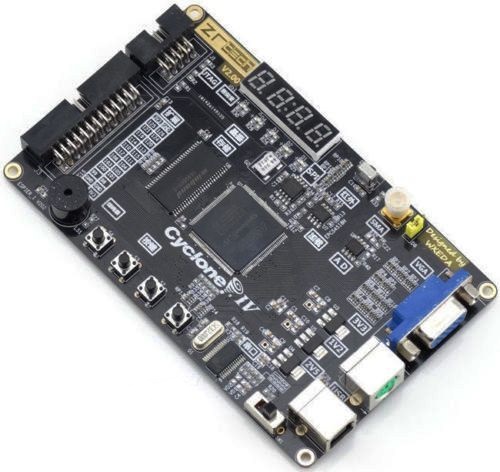
FPGA development board (EP4CE6E22C8N)
There are quite a few FPGA development boards and the two main FPGA manufacturers are Xilinx and Altera. You can buy cheap dev boards for both manufacturers in ebay for $40. In this project I’ve used a development board with an Altera Cyclone IV FPGA device (EP4CE6E22C8N), like this one:

This board has plenty of peripherals like vga output, PS/2, SPI flash, SDRAM, 4 digit 7-segment display, 4 tact buttons, A/D, IrDA, LEDs, buzzer and USB-to-UART. So you can build several stupid projects with this beauty.
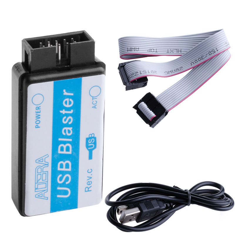
USB Blaster (programmer)
Finally, you’re going to need a programmer. Again ebay has plenty of cheap USB programmers. Search for `Altera USB Blaster’ and you’ll find many around with $3-4, like this one:

Quartus Prime Lite Edition
To write your awesome software you’ll need the Quartus Prime Lite Edition IDE. This IDE will look a bit strange, if you’re coming from the embedded software world. FPGA engineers have a quite different taste on how an IDE should be look like, but after spending some time with it, then everything makes sense and it’s fun to work with.
Making the stupid project
Well, no much things to say here. I mean, you don’t have to make any connections, no soldering, nothing. Just plug the USB power cable on the board, connect the USB Blaster to on the 10-pin header and to you computer USB port, download and install the Quartus and then git clone the following the project and open it in the Quartus.
https://bitbucket.org/dimtass/fpga_clock
I’ve used Quartus in both Linux and Windows and I’ve programmed the board just fine. The result is a digital a clock. Actually, is a powerful FPGA on a board with couple awesome peripherals and all it does is flashing a few LEDS every second and display the time on the 7-segment. That’s the definition of a stupid project.
This is a short video of the clock:
Conclusion
FPGAs are fun. Especially, when it’s not your everyday job and it’s just a hobby. From the few things that I’ve seen is easy to make simple projects, is nice to know how they work and how you program them and it can be an agonising pain if it’s your job. There are so many things that can go wrong in there, that sometimes is miracle that a project works. Time constrains, parallelisation and several other things in the silicon that are sensitive in so many parameters. It’s hell. But now I have a $40 digital clock and I can shout to the world that I’m also an expert on FPGAs. FPGAs are addictive when you start with them, but when you scratch the surface and go a bit deeper, then you’re glad it’s not your everyday job.
Have fun!
Comments powered by Disqus.