Hacking an RS232/485 to ETH board
Intro
It’s time for another stupid project. This time we’ll do some hacking and by that I mean that we’ll take an already existing device and alternate it to do something else. A couple of years ago, I’ve found in e-bay some nice and cheap RS232/485 to ethernet modules from usriot and I’ve bought them to play with them at some point as they had an LPC1114 controller, a DM9000 ethernet MAC and an UART interface configured as RS232 or RS485. You can do a lot of great stuff with this combo. Anyway, I decided to implement an ArtNet DMX512-A controller to controll DMX loads via Ethernet. To do that I needed a TCP/IP stack and also implement the basics of the ArtNet protocol. For the TCP/IP stack I’ve chosen uIP as it the most light-weight stack and it’s also easy to expand, as it doesn’t support all the things are needed (like udp broadcast and multicast). Also, ArtNet is an open and well defined protocol that can be found here (the link points always in the latest version which now is 4 but at the time I’ve written the code was in v.3).
Components
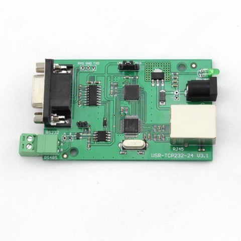
USR-TCP232-24
All you actually need is a USR-TCP232-24 board. Although I’ve bought it a couple of years ago you can still find many if those especially in alibaba and quite cheap. It’s a nice board no matter what and it can be used for several other stupid projects (for example a KNXnet/ip device would be a good candidate). The company that manufactures these modules it seems that it changes their hardware quite often. At some point they’ve changed their USR-TCP232-24 (LPC1114+DM9000) with the USR-TCP232-410S and USR-TCP232-410-PCBA (TM4C129EKCPD w/ integrated MAC) and now they don’t officially sell only PCB board but they sell the device with the casing. I’ve also bought two of the USR-TCP232-410-PCBA to play with at some point as they have a more powerful Cortex-M4 processor. Anyway, this is the board.
PX24506 DMX512 Decoder Driver
You don’t really need this for the project if you already have a DMX512A compatible device. If you don’t then you can buy a cheap RGB LED strip from ebay and a DMX512A decoder driver and have fun. A nice and quite cheap driver is the PX24506. It has 3x 3A channels for RGB, DMX-in and DMX-out to connect drivers in series and you can set the DMX address with a binary switch. I really like this driver. Uber Chinese tech stuff here. This is the driver.
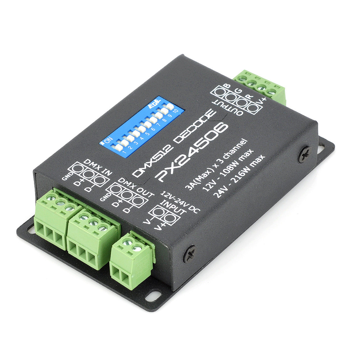
You can find this beauty sold in tons in ebay.
Also, there are other two alternatives which I haven’t test them yet. They’re much cheaper but you can’t program the DMX address easily. You may find them as DM-103 and DM-104 in ebay or if you search for generic DMX512 Decoder Boards. This is how they look like.
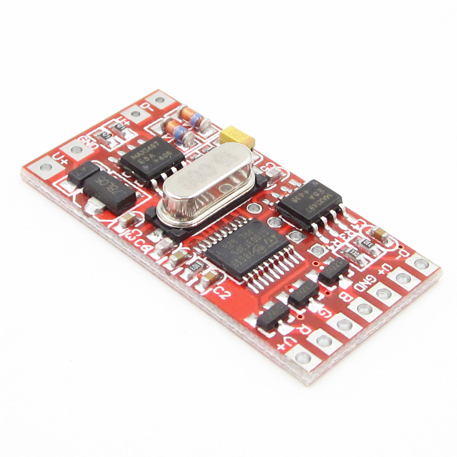
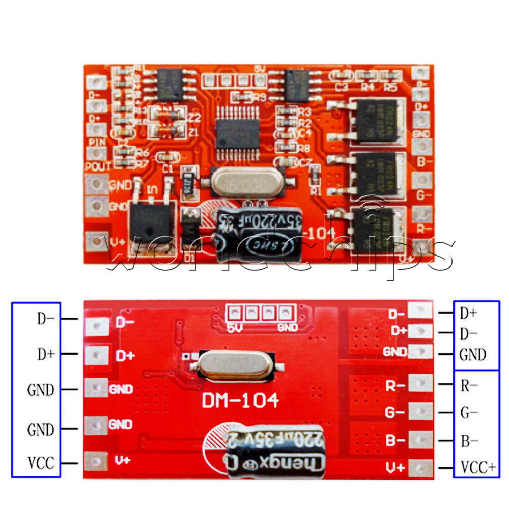
Their difference is that the DM-104 is rated at 144W. The processor on these is an STM8 so you may also write a custom firmware in there (just saying).
Making the stupid project.
To make this project you need the free version of the MDK-ARM Keil compiler, the source code from my github repo here and the flash magic tool to flash compiled HEX file. The size of this project is not that large, therefore the evaluation MDK-ARM license is just fine. So, you need to load the project, build it and then flash the board. I’ve used an older uVision version (v4) to build this project, so in case of the v.5 you need to install the legacy packages that support the LPC1114 controller and then import the project file.
So, first step is to install the evaluation version of MDK-ARM and Flash Magic. Then clone the source code repo from github, open the dmx_tcp.uvproj and compile the project. The output dmx_tcp.hex will be created in the ./Flash folder, therefore use Flash Magic to flash it on the device. To do that, remove the power and place the jumber in the UPD position. The LPC series have a serial bootloader, so the next time you apply power the bootloader will load and then you can use the Flash Magic to flash the board. After that place the jumber again in the GND position.
When the jumber is on the GND position then the device functions in DMX512A mode using the RS485 to send the data. When the jumber is places in the CFG position then the device enters the debug mode. You can see what the debug mode does in the source code and also you can see the supported RS232 commands in UART_Handler() function in main.c. In the debug/configuration mode you can set use an RS232 terminal or console to configure the device. I’ve also created a file (terminal_macros.tmf) which contains a few macros that you can use with Br@y's terminal. Connect an RS232 cable to the device and enter HELP and Enter key to print the available commands. Anyway, use the macros and the Br@y's terminal, trust me, it’s the easiest way.
In the normal mode (jumber in GND) the device is running in one of the two supported modes that you can set in the configuration mode. The mode 0 (DMX_TCP_MODE_ASCII) is a plain ASCII TCP socket that you can connect and handle the DMX by sending simple ASCII commands. The supported commands are in the connection_handle_ascii() function in connectio.c file.
Mode 1 (DMX_TCP_MODE_BINARY) is the default ArtNet protocol mode. When this mode is used then you need a software that can control DMX universes using ArtNet, such the ArtNetominator. I’ve also implemented the ArtNet configuration protocol, so you can configure the IP and the device name by using the ArtNetominator.
Conclusion
This is a nice stupid project if you want to hack an RS232/485 to Ethernet device to implement a 1-Universe DMX Artnet gateway. There’s absolutely no meaning to do that, though! I mean, you can buy a Chinese 4x DMX universe device that supports E1.31(sACN) for ~$80 which is dirt cheap. There’s absolutely no reason to really make this stupid project. In case you want, though grab the code and play around with it.
Have fun!
Comments powered by Disqus.