Component database with LED indicators [Updated]
Intro
Update: it’s being almost 10 months since I’m using this project and it works great with no issues. The firmware is robust and the LED strips are great, too.
Finally, a really stupid project! You know, I was worrying that this blog is getting too serious with all those posts about machine learning and DevOps. But now it’s time for a genuine stupid project. This time I’m going to describe why and how I’ve built my personal component database and how I’ve extended this and made some modifications to make it more friendly.
For the last 20 years my collection of components, various devices and peripherals has grown too much. Dozens of various MCUs, SBCs, prototype PCBs and hundreds of components like ICs, passive devices (resistors, capacitors, e.t.c.), and even cables. That’s too much and very hard to organize and sort. Most EE and embedded engineers already feel familiar with the problem. So, the usual solution to this is to buy component organizers with various size of storage compartments and some times even large drawers to fit the larger items. Then the next step is to use some invisible tape as labels on each drawer and write what’s inside.
While this is fine when you have a few components, when the list is growing too much then even that is not useful. Especially, after some time that you forgot when some stuff are really located then you need to start reading the labels on every drawer. Sometimes it may happen that you pass the drawer and then start from beginning. If you’re like me this can get you angry after few seconds of reading labels. You see, the thing is that when you have to start looking for a component is because you need it right now as you’re in middle of something and if you stop doing the important task and start spend time searching for the component, which is supposed to be organized, then you start getting pissed. At least I do.
Therefore, the solution is to have a database (DB) that you can search for the component and then you get its location. Having a such a database is very convenient, because you can also add additional information, like an image of the component, the datasheet and finally create a web interface that is able run queries in the db and display all those information in a nice format.
For that reason a few years back in 2013 I’ve created such a database and a web interface for my components and until now I was running this on my bananapi BPI-M1. Until then though, the inventory has kept growing and recently I’ve realized that the database is not enough and I need to do something else in order to be able to find the component I need a bit faster. The solution was already somewhere in those components I already had, therefore I’ve used an ESP8266 module and an addressable RGB LED strip.
Before continue with the actual project details, this is a video of the actual result that I got.
If what you’ve just see didn’t make any sense, then let’s continue with the post.
Components
This is a list of the components that I’ve used for this project
BPI-M1
This is the old classic BPI-M1
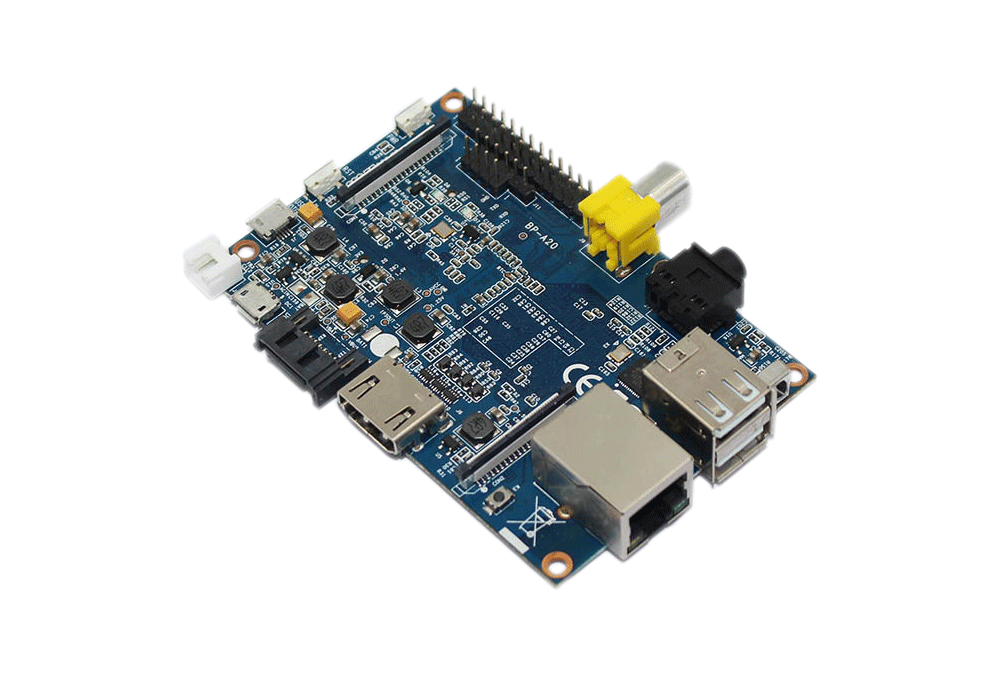
You don’t have to use this exact SBC, you can use whatever you have. The reason I’ll use this in this example is just because it’s my temporary file server and already runs a web server. BPI-M1 is the first banana-pi board and it’s known for its SATA interface, because at that time is was one of the very few boards that had a real SATA interface (and not a USB-to-SATA or similar). Not only that, but also has a GbE and you can achieve more than 60 MB/sec on a GbE network, which is quite amazing as most of the boards are much slower. I’m using this SBC as my home web server and home automation server, as also a temporary network storage for data that are not important and also I’m running a bunch of services like the DDNS client and other stuff. Therefore, in my case I already had that SBC running in the house for many years. Since 2014 it was running an old bananian distro and only recently I’ve updated to one of the latest Armbian distros.
As I’ve mentioned you can use whatever SBC you like/have, but I’ll explain the procedure for BPI-M1 and Armbian, which it should be the same for any SBC running Armbian and almost the same for other distros.
Of course you can use any web server in the internet if you already have. I’ll explain later why there’s no problem to host the web interface in a web server on the internet and at the same time running the ESP8266 in your local network.
Components organizer
This box has many names as components organizer, storage box with drawers, storage organizer, e.t.c. Whatever the name is, this is how it looks like:
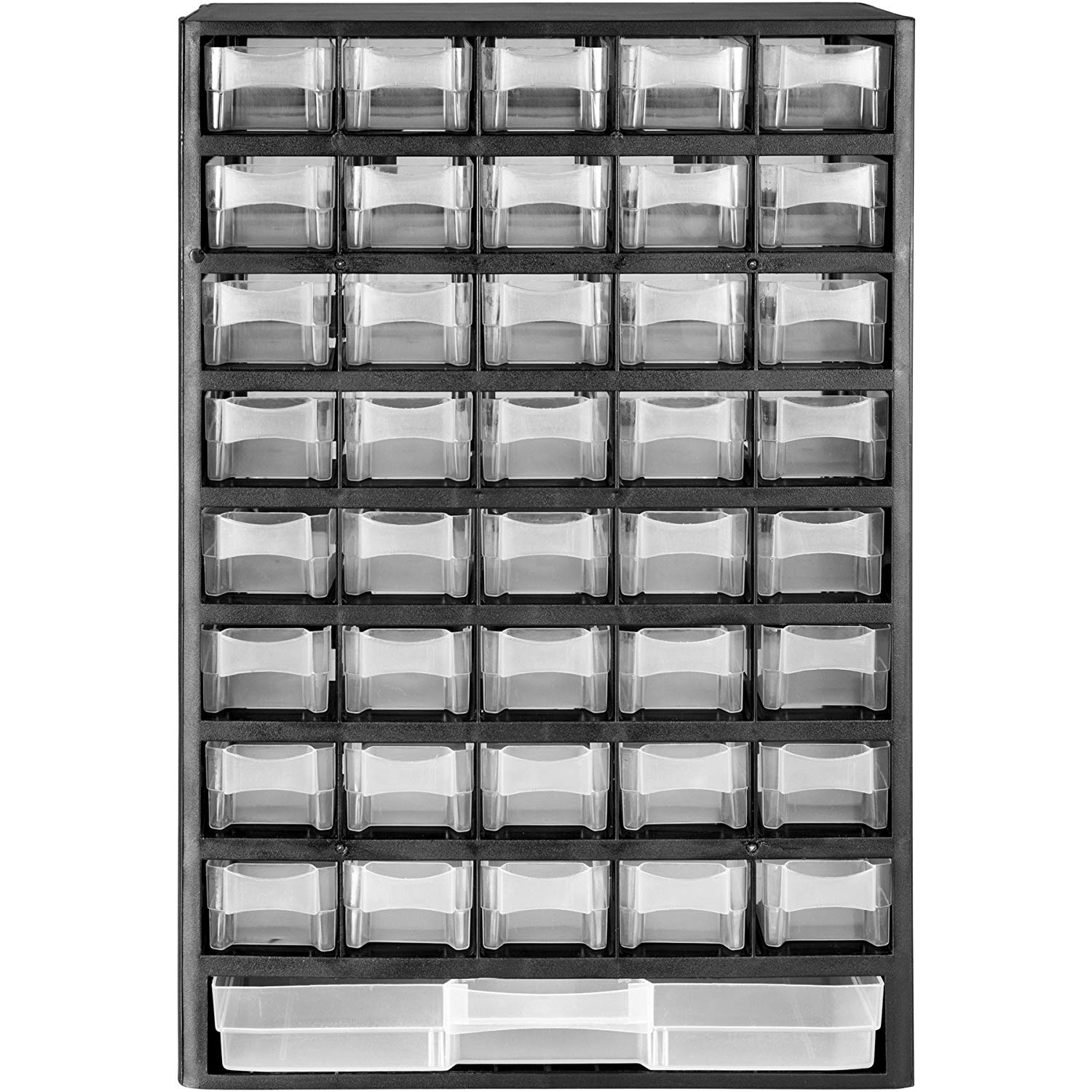
There are many small plastic drawers that you organize your components. I mean you know what it is, right? I won’t explain more. As you’ve seen on the video when the LED is turning on then the drawer is also lit. This kind of white or transparent plastic (I don’t know the proper English name) is good for this purpose as it’s illuminating with the color of the RGB light. So prefer those organizers instead of a non-transparent.
WS2812B RGB LED strip
This is the ws2812b RGB LED strip I’ve used.
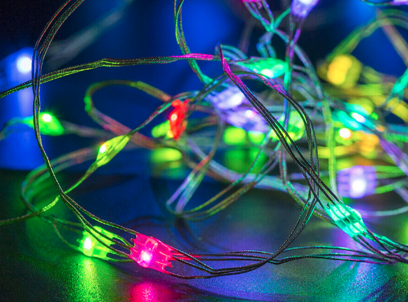
You probably are more familiar with this strip format.
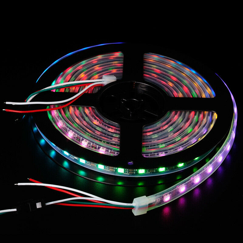
But it’s important to use the first strip for the reasons I’ll explain in a bit.
The good ol’ ws2812b is one of the first addressable RGB LEDs and until today it’s just fine if you don’t need to do fancy animation and generally any fast blinking on large RGB strips. Also, it’s not really addressable but it seems like that from the software perspective. The reason that ws2812b it’s not really addressable is because you can control each LED individually, but if you want to change a LED color you need to send all the LED values on the strip (actually the colors up to the wanted index). That’s because the data are shifted from one LED to the next one in the chain/strip, so every 24-bits (3x colors, 8-bit/color) the data are shifted to the next LED.
As you can imagine this strip is placed in the back of the organizer in order to illuminate the drawers. The reason you need the first format is that each drawer has a distance from the next one. The first strip has 10 LEDs/meter which means 1 LED every 10cm which is just fine for almost any organiser (except the bottom big drawer). The second strip has 60 LEDs/meter which means that in that case behind every drawer will be more than 1 LED, which is great waste. So if you used the second strip you would either have to cut every LED and resolder it using an extension cable or skip LEDs and use a more expensive strip. Anyway, it doesn’t make sense to use the second strip, just use the first one.
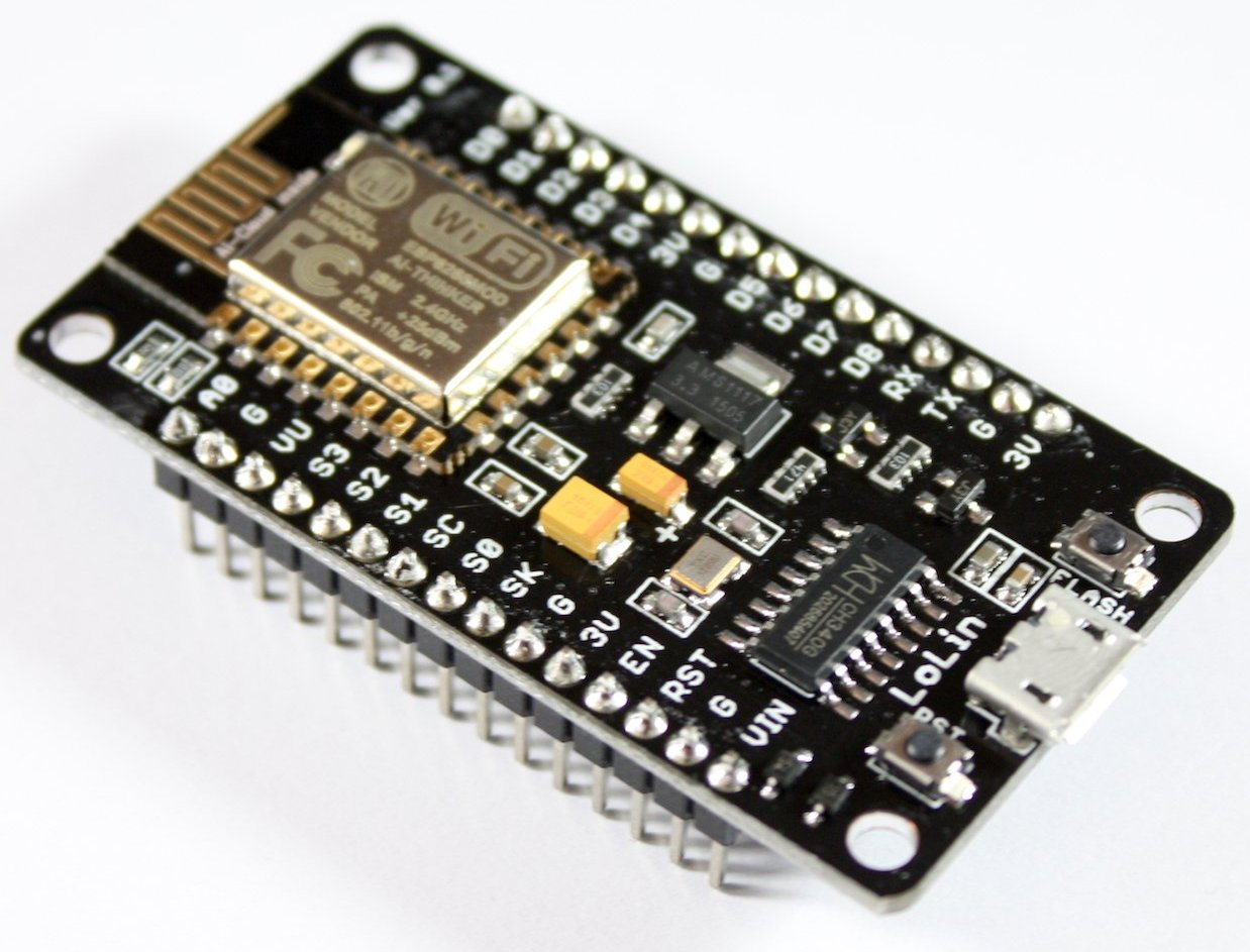
ESP8266
The ESP8266 is an MCU with WiFi and there are many different modules with this MCU as you can see here. Also there are many different PCB boards that use some of those variations, for example the ESP-12F can be found on many different PCBs with the most known being the NodeMCU. In this project I’ll use the NodeMCU, because it’s easier for most of the people to use as you can use a USB cable to power the module and also flash it easily and do development using the UART for debugging. In reality though, since I have a dozen of ESP-01 with 512KB and 1MB, I’m using that in my setup. I won’t get into the details for the ESP-01 though, because you need to make different connections in order to flash it. Since you only need 2 pins, one for output data in the strip and one for reset the firmware configuration settings to default, then the ESP-01 would fit fine, but with some ticker for make the pins usable.
Anyway let’s assume that we’ll use the NodeMCU for now, which looks like that
Project details
Let’s see a few details for the project now. Let’s start with the project repo which is located here:
https://github.com/dimtass/lab-database-web-interface
In there you’ll find a few different things. First is the www/ folder that contains the web interface, then it’s the esp8266-firmware that contains the firmware for the NodeMCU (or any ESP-12E) and finally there is a dockerfile that builds an image with a webserver that you can use for your tests. I’ll explain every bit in more detail later, but for now let’s focus on how everything is connected. This is the functional diagram.
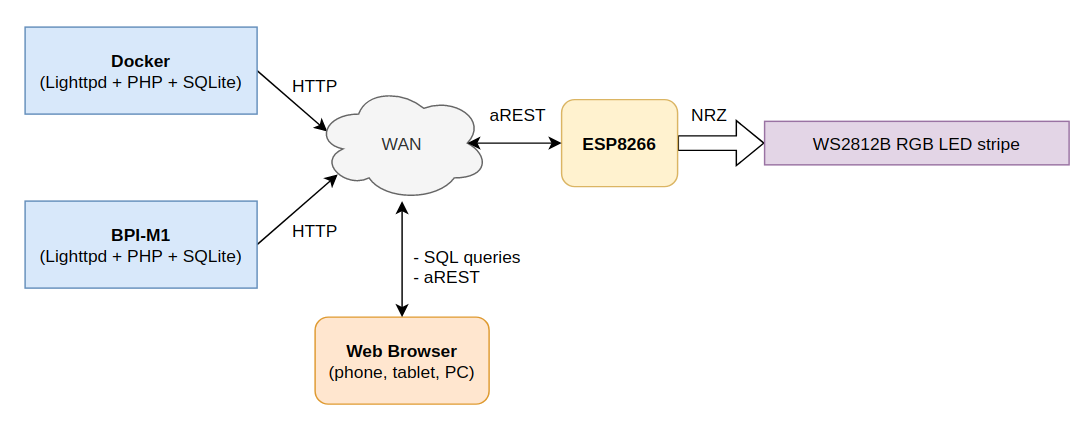
As you can see from the above diagram there’s a web server (in this case Lighttpds) with PHP and SQLite3 support that listens on a specific port and IP address. This server can run on either a docker container (for testing or normal use) or an SBC. In my case I did all the development with docker and after everything was ready I’ve uploaded the web interface on the BPI.
Then from the diagram it’s shown that any web browser in the network can have access to the web interface and execute SQL queries to display data. The web browser is also able to send aREST requests via POST to a remote device that runs an aREST server, which in this case this is the ESP8266.
Finally, you see that the ESP8266 is also connected in the network and accepts aREST requests. Also it drives a ws2812b RGB LED strip.
So what happens in normal usage is that you open the web interface with your web browser. By default the web server will return a list with all the components in the database (you can change that in the code if you like). Then you can write in the search text field the keyword to search in the database. The keyword will be looked up in the part name, the description or the tag fields of the database’s records (more for the db records later) and the executed SQL query will return all the results and will update the web page with the entries. Then depending on the record you can view the image of the item, download the datasheet, or if you’ve set an index in the Location field in the db table then you’ll also see a button with label Show.
The image and the datasheet are stored in the web server in the datasheet/ and images/ folder. Actually the image that you see in the list is the thumbnail of the actual image and the thumbnails are stored in the thumbs/ folder. The reason of having thumbnails is to load the web interface faster and then if you click on a thumbnail then the actual image is loaded, which can be in much better resolution with finer detail. By default the thumbs are max 320x320 pixels, but you can also change that as you prefer.
When pressing the Show button, then a javascript function is executed on the web browser and an aREST request is posted to the IP address of the ESP8266. Then the ESP8266 will receive the POST and will execute the corresponding function, which one of them is to turn on a LED on the RGB strip using the passing index from the request. Then the LED will turn on and will remain lit for a programmable time, which by default is 5 secs. It’s possible to have more than one LED lit at the same time and each LED has it’s own timer. You can also lit all the LEDs at the same time with a programmable color in order to create a more romantic atmosphere in your working environment…
Finally, you can send aREST commands to change the ESP8266 configuration and program the available parameters, which I’ll list later.
Web interface
The web interface code is in the www/lab/ folder of the repo. In case you want to use it in your current running web server, then just copy the lab/ folder to your parent web directory. Although the web interface has quite a few files, it’s very basic and simple. You can ignore the css/ and the js/ folders as they just have helper scripts.
Since the web interface runs on your web browser then it’s necessary that your device (web browser) is on the same network and subnet with the ESP8266. Therefore, you can also have the web interface running for example on your VPS (virtual private server) on the internet and the aREST posts will work fine as long you’re in the same network with the ESP8266.
The main file of the web interface is the www/lab/index.php. This is the file that displays the item list, sends SQL queries to the web server and also posts aREST commands to ESP8266. In the $(document).ready function you can see that there’s a PHP code that first read the ESP8266IP.txt file. This file is in the lab/ folder of the web server and it contains the IP of the ESP8266. By default is set to 192.168.0.42, therefore you need to change that with the IP of your ESP8266 device. In the same function the web browser will try to detect if the ESP8266 is actually on the network and if it’s not then you’ll get a warning.
The function turn_on_led(index) function sends a POST to the ESP8266 aREST server with the index of the LED that needs to turn on.
The html form the the id searchform is the form that handles the Search part area in the web interface. When you write a keyword in there and press the Search button, then this code is executed:
1
2
3
4
5
6
7
8
9
// by default list all the parts in the database
$sql = "SELECT * from tbl_parts";
// check if a submit is done
if(isset($_POST['submit'])){
  // check for valid search string
  $part=$_POST['part'];	// get part
  $sql = 'SELECT * from tbl_parts WHERE Part LIKE "%'.$part.'%" OR Description LIKE "%'.$part.'%" OR Tags LIKE "%'.$part.'%"';
}
echo '<br>Results for query: '.$sql.'<br><br>';
This will reload the content of the page and will create a list of items with the results. The code for that is just right below the above snippet in the index.php file. The last interesting code in this file is that one here:
1
2
3
if (!empty($row['Location']) && $ip) {
  echo '<button onclick="turn_on_led(' . $row['Location'] . ')">Show</button>';
}
This code will add the Show button if the proper field in the DB is set and the ESP8266 is on the network.
There are also other two pages that are important and these are the web/lab/upload.html and web/lab/upload.php files. These two pages are used to add new records in to the database. The upload.html page is opened in the web browser when you press the Add new part button and this is what you see
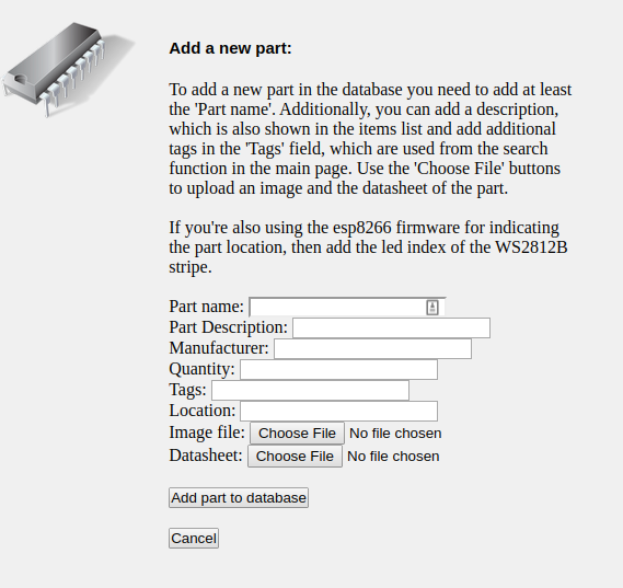
There you fill all the text boxes you want and also select an image file and a datasheet if you like to upload to the server. When you fill all the data then you press the Add part to database button and if everything runs smooth then you’ll see this
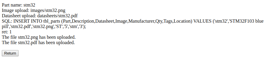
This means that a new record is inserted in the database without error and if you press the Return button then you get back to the main page. There’s a problem though. I wouldn’t use this way to create all the records in the database because it’s very slow and it will take a lot of time. Also with this way you can’t edit or update a record, therefore the preferred way to initially set up your database with many components is to use program that can open and edit the database.
In my case I’m using Ubuntu, therefore I’ll explain how to do that with Linux, but in case you’re a Windows user then you can use this the DB Browser for SQLite. To install that in Ubuntu just run this command:
1
sudo apt install sqlitebrowser
Then from your applications run the DB Browser for SQLite and when the program starts open the www/lab/parts.db and click on the Browse Data tab. In there you’ll see this
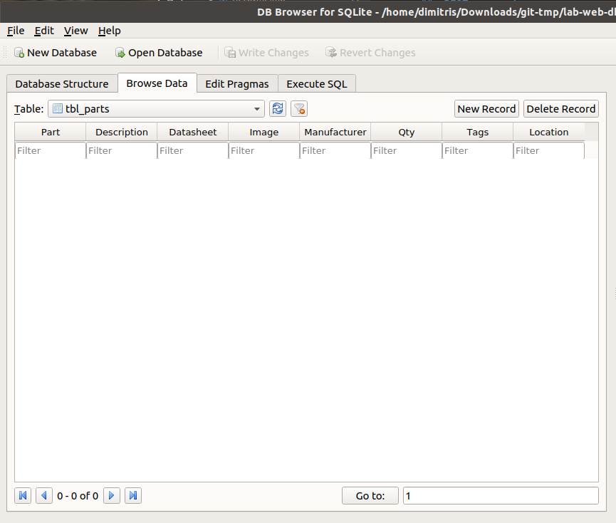
Now this is a much easier way to add records, but also there’s a drawback because the files won’t be uploaded and also the thumbnails won’t be created automatically. But there’s a solution about that, too.
So, the best way to fill your database is to run the docker web server as this will help you to test and also add the records faster. I’ll explain how to run the docker image in the next section, so for now I assume that you already do this, so I won’t interrupt the explanation and the process.
The DB has the following fields:
- Part
- Description
- Datasheet
- Image
- Manufacturer
- Qty
- Tags
- Location
This is an example of a record as shown in the web interface
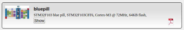
In this the bluepill is the the Part field, the long description is the Description field and the image and datasheet icons are shown because I’ve added the image name in the Image and Datasheet fields. The Manufacturer, Qty fields are not really important and are not shown anywhere. The Tags field is used as an extra tag for DB SQL search queries and finally if you set a number in the Location field then the Show button is shown and that number is the index of the LED on the addressable RGB strip.
What is important is that you copy the image file in the web/lab/images folder and the datasheet pdf file in the web/lab/datasheets folder, but in the DB fields you only write the filename including the extension, for example blue-pill.png and blue-pill.pdf. Finally, after you fill the DB with all your parts and items then to create the thumbs you can run the www/lab/scripts/batch_resize.sh script from the parent directory of the repo like this
1
2
cd www/lab
./tools/batch_resize.sh
This script will create the thumbnails in the www/lab/thumbs folder. You can change the default thumb size like this:
1
MAX_WIDTH=240 MAX_HEIGHT=240 ./tools/batch_resize.sh
After you’ve finished with the DB changes, then don’t forget to click the Write Changes button in the program and then you can upload all the files to your web server after you’ve done testing with the docker web server image. Remember that if you click on the image in the item list then the original image is loaded and opens in the browser.
Testing with the docker web server
As I’ve mentioned earlier, testing with the actual web server that runs on your SBC or web server is quite cumbersome as you first need to set up the server and then it’s still not very convenient to edit the files remotely or edit them locally and then upload them to test. You can do it if you like, but personally I would get tired with this soon. Therefore, I’ve added a Dockerfile in the repo which is located in the docker-lighttpd-php7.4-sqlite3/ folder. To build the docker image run the following command
1
docker build --build-arg WWW_DATA_UID=$(id -u ${USER}) -t lighttpd-server docker-lighttpd-php7.4-sqlite3/
This command will build a docker image with the Lighhtpd web server, PHP 7.4 and SQLite which can be used for your tests. After the image is built you also need the docker-compose tool, which is not installed with docker and you need to install it separately with these commands
1
2
sudo curl -L "https://github.com/docker/compose/releases/download/1.25.0/docker-compose-$(uname -s)-$(uname -m)" -o /usr/local/bin/docker-compose
sudo chmod +x /usr/local/bin/docker-compose
If you don’t use Linux then see here how to install docker-compose.
So, after you’ve built the image and you installed docker-compose then from the root directory of the repo you can run this command:
1
docker-compose up
After running this command you should see this output:
1
2
3
4
Creating lab-web-db_webserver_1 ... done
Attaching to lab-web-db_webserver_1
webserver_1  | [14-Jan-2020 14:43:13] NOTICE: fpm is running, pid 7
webserver_1  | [14-Jan-2020 14:43:13] NOTICE: ready to handle connections
This command will actually run a container with the web server and it will also mount the web interface folder in the /var/www/html/lab folder inside the container and will also override the /etc/lighttpd/lighttpd.conf and /usr/local/etc/php/php.ini files in the container. You can also open the docker-compose.yml file to see the exact configuration of the running container. Now to test the web server you need to get the IP of the server and to do that the easiest way is to run this command on a new console window/tab
1
docker-compose exec webserver /bin/sh
This command will get you in the container’s console, so you can run ifconfig and get the IP of the container, for example:
1
2
3
4
5
6
7
8
743e05812196:/var/www/html# ifconfig
eth0      Link encap:Ethernet  HWaddr 02:42:AC:12:00:02
          inet addr:172.18.0.2  Bcast:172.18.255.255  Mask:255.255.0.0
          UP BROADCAST RUNNING MULTICAST  MTU:1500  Metric:1
          RX packets:15 errors:0 dropped:0 overruns:0 frame:0
          TX packets:0 errors:0 dropped:0 overruns:0 carrier:0
          collisions:0 txqueuelen:0
          RX bytes:2430 (2.3 KiB)  TX bytes:0 (0.0 B)
In this case the IP of the container is 172.18.0.2 which means that you can open the web interface to your web browser using this URL:
That’s it! Now you can edit your files with any text editor and add stuff in your DB and just refresh the web page in your browser to load the changes. That way the testing is done much easier.
Firmware
Finally there’s the firmware for the ESP8266! I’ll try to explain a few things about the firmware here, but generally is very easy and straight forward. The firmware is in the esp8266-firmware/ folder in the repo. I’ve used Visual Studio Code (VSC) and the platform.io (PIO) plugin to write the firmware as it’s very easy to do stupid projects fast and I’ve also used the Arduino framework with the ESP8266. The nice thing with the PIO plugin in VS Code is that you don’t need to find the libraries I’ve used yourself, as the plugin will handle those.
First open the esp8266-firmware/ folder in VSC and then install the PIO plugin from the extensions in the left menu of the IDE. When you do that, then click on the alien head in the left menu, which opens the PIO menu in which you see the project tasks. Press the Build and see what happens. If that builds OK, then you’re good to go, but if it complains about missing libraries then click on the View -> Terminal menu of VSC and then in the terminal run those two commands:
1
2
pio lib update
pio lib install
Those commands should install the missing libs which are the FastLED and aRest.
A note about aREST here. Although the library claims that it’s a true restful API it’s not! There’s no any control about GET, POST, UPDATE and all the other supported rest API commands. Whatever command you use, the aREST handles them the same in the same callback… That’s actually a pity because I had to implement some commands twice in order to implement the POST/GET functionality. Anyway, a small rant, but also I don’t intend to fix this myself…
The main course file is the src/main.cpp. There a few things going on in there, but generally you need to define a few things before you build the firmware, which are:
def_ssid: The default SSID of your routerdef_ssid_password: The SSID passworddef_led_on_color: The default RGB color when a LED is activateddef_led_off_color: The default RGB color for deactivated LEDRESET_TO_DEF_PIN: The pin is used to reset the configuration to the default valuesSTRIPE_DATA_PIN: The pin that drives the RGB LED stripNUM_LEDS: The number of LEDS in the strip. This is the number of the drawers of your component organizer.
Normally, you would only change initially the def_ssid and def_ssid_password for testing and then at some point also the def_led_on_color.
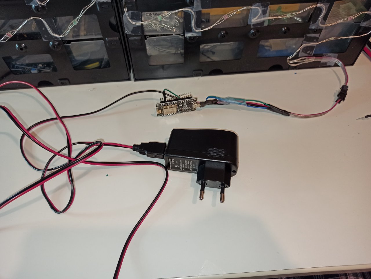
Now you need to connect everything together, which is quite simple. Use a +5V power supply that can provide the needed power and current for the LED strip. In my case I see approx 2.5 Amps with 100 LEDs when are set to white which is the max. That means that I need at least a 3A PSU (or 15W). Now, connect the +5V and GND of the WS2812B strip to the PSU and then also do the following connections
| ESP8266 (NodeMCU) | WS2812B |
|---|---|
| D2 | Din |
| GND | GND |
Also connect the D1 pin of the NodeMCU to GND via a 4K7 resistor. This pin is used for reseting the configuration to the default values and when it’s connected to the GND then it’s the normal operation and when is connected to +3V3 then if you reset the ESP8266 then the default configuration will be loaded. Always remember to connect the resistor again to the GND after reseting to defaults.
Finally connect a USB cable to ESP8266 and your computer or a USB power supply in normal use.
Getting back to the code, the load_default_configuration() will load the default configuration and this function is called either if a false configuration is found (e.g. empty or corrupted conf) or when the D1 pin is HIGH.
When the program starts and the main function is loaded, then the serial port is configured and then the D1 input pin. Then the configuration is loaded from the EEPROM (actually the flash in case of ESP8266) and next the aREST API is configured with the exposed functions and the internal variables. Then the module is connected to the SSID via WiFi and the main 100ms timer is set to continuous run. This timer is used for all the timeout actions of the LEDs. Finally, the WS2812B strip is initialized and all LEDs are set to the led_off_color value, which is Black (aka turned off) by default.
In the main loop, the code handles all the aREST requests, checks if it needs to save the configuration in the EEPROM (=flash) and also check the timeout of the LEDs and in any is activated it check the timeout and when it’s reached it turns off the LED.
The rest of the functions with the ICACHE_RAM_ATTR prefix are the callbacks for the aREST API. This prefix in the function is actually a macro that instructs the linker to place those functions in RAM instead of flash, so the code is accessed faster. So let’s see now the supported commands which are listed in the following table
| Command | Description |
|---|---|
| led_index | The index of the LED to turn ON |
| led_on_color | The integer value of the CRGB color for ON |
| led_off_color | The integer value of the CRGB color for OFF |
| led_on_timeout | The integer value of the LED timeout in seconds |
| led_ambient | The integer value of the CRGB color for the ambient mode (for real-time selection) |
| save_led_ambient | The integer value of the CRGB color that is saved as the default ambient color |
| enable_ambient | Enables/disables the ambient mode |
| wifi_ssid | The WiFi SSID |
| wifi_password | The WiFi password |
You can find the CRGB value for each supported color in the FastLED library file which is located in .pio/libdeps/nodemcuv2/FastLED_ID126/pixeltypes.h. Then you can use a calculator to convert HEX values to integers.
In case you want to play around with the aREST commands, you can use a REST client like insomnia or you can use your browser and use the address bar to send GET commands. In any case the URL for each command has the following format:
1
http://IP_ADDRESS/COMMAND?params=VALUE
Therefore if the ESP8266 IP address is 192.168.0.42 and you want to use the led_index command to turn on the 2nd LED of the strip, then paste this line to your web browser’s address bar and hit enter.
1
http://192.168.0.42/led_index?params=2
Or if you want to set the led_on_color to SkyBlue (which according to pixeltypes.h is 0x87CEEB in HEX or 8900331 in integer), then
1
http://192.168.0.42/led_on_color?params=8900331
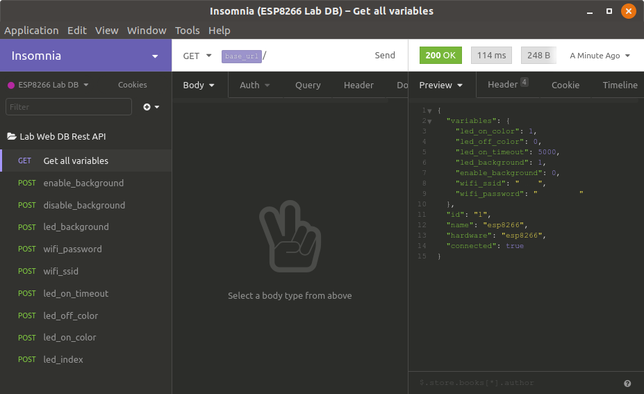
Finally, you can get all the current aREST variable value with this URL:
1
http://192.168.0.42/
This is will return something like this:
1
2
3
4
5
6
7
8
9
10
11
12
13
14
15
{
  "variables": {
    "led_on_color": 1,
    "led_off_color": 0,
    "led_on_timeout": 5000,
    "led_ambient": 1,
    "enable_ambient": 0,
    "wifi_ssid": "    ",
    "wifi_password": "         "
  },
  "id": "1",
  "name": "lab-db",
  "hardware": "esp8266",
  "connected": true
}
Actually, since I’m using Insomnia for my tests, this is an example output from the tool.
Finally, I would like to mention that the configuration, although you see that I’m using the EEPROM.h header and functions, is actually stored in the flash. The configuration is a struct and specifically the struct tp_config which has several members, but the important are the preamble, the version and the crc. The preamble is just a fixed 16-bit word (see FLASH_PREAMBLE) which is 0xBEEF by default and it’s used by the code the verify that when it copies the EEPROM in to the struct then it’s a valid struct. The configuration version is used to compare the EEPROM configuration version with the firmware version and if those are different (i.e. because of a firmware update) then the check_eeprom_version() function is responsible to handle this. Therefore, if you add more variables in the configuration then the size of the configuration will change, which means that you need bump up the version in the firmware code and then also handle this in that function in case you want to preserve the current configuration (e.g. WiFi credentials), otherwise the easy way to just restore the defaults, which is already happens in the code. Finally, the crc is the checksum of the configuration and if that is not correct when reading the data from the EEPROM then again it’s an error condition and by default is handled by reset the configuration to defaults.
To build and upload the code now, just select the PIO in the activity bar in the left. There you would see the project tasks which include Build and Upload and Monitor. If you can’t see those then you probably opened the top repo folder which means that you need to open only the esp8266-firmare/ folder in VSC and then you should be able to see those tasks. By clicking the build task the terminal should open in the bottom of the UI and you should get something like this
1
2
3
4
5
6
7
8
9
Building in release mode
Retrieving maximum program size .pio/build/nodemcuv2/firmware.elf
Checking size .pio/build/nodemcuv2/firmware.elf
Advanced Memory Usage is available via "PlatformIO Home > Project Inspect"
DATA:    [====      ]  38.2% (used 31316 bytes from 81920 bytes)
PROGRAM: [===       ]  28.1% (used 293584 bytes from 1044464 bytes)
====================================================== [SUCCESS] Took 2.26 seconds ======================================================

Terminal will be reused by tasks, press any key to close it.
That means that the firmware is ready to be uploaded to the ESP8266, so click the Upload and Monitor task from the left menu and the flash procedure will start. There’s a chance that the USB Comm port is not found, in this case if you’re using Linux it means that you need to add the proper udev rules (see how you do this here).
Testing
Before you proceed with installing the LEDs in the components organizer, you first need to check that everything works as expected. Therefore, first you need to create your database and the easiest way as I’ve mentioned is using the docker image and the DB Browser for SQLite. After you’ve done with the database then you can do the tests with the ESP8266 in the docker container, so first you need to make the proper connections and connect the WB2812B led stripe with the ESP8266.
For this post I’ll use the NodeMCU (actually a clone) with the ESP-12E module. Just connect the D1 pin with a 4K7 resistor to GND, also the GND of the module with the GND of the WS2812B, the D2 pin of the ESP8266 with the Din pin of the strip and finally connect the ESP8266 with a USB cable to either your PC or to USB charger. Of course, before that you need to verify that your firmware is flashed and the ESP8266 is able to connect to the WiFi router and also responds to the http://ip-address/ aREST command with it’s current configuration.
Finally, connect the WS2812B to a +5V power supply that can provide enough current. Just a note here, although the ESP8266 is a 3V3 device and the WS2812B is a 5V, you shouldn’t expect any problems with the voltage difference and you shouldn’t need a level translator. From my experience I never had any issues with any 3V3 MCU and the WS2812B.
After all connections are made and everything is powered up, then you can use your desktop browser (not your smartphone) that runs the docker container and test that the LED is lit on when you press the Show button of a component that has an index in the Location field in the DB. If that works then you’re good to go and install the LED strip in the back of the components organizer.
LED strip comparison and details
As I’ve mentioned I didn’t use the standard 30/60/144 LEDs per meter strips that you usually find in ebay. This is a 10 LEDs/meter strip, which means each LED is 10cm away from the other. That is perfect for this project for many reason but also has a drawback, which I’ll discuss later.
For comparison, this a photo of the 10 LEDs/m strip and another 60 LEDs/m I have. The comparison is between them and an ESP-01 module, which is one of the smallest ESP8266 modules available.
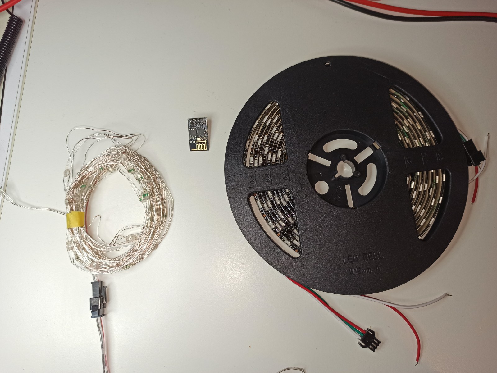
The strip on the left is 5m length, which means it counts 50 LEDs and the one on the right side is 4m length and it counts 240 LEDs. The good thing about the strip on the left is that much more thinner and flexible and the distance between the LEDs is ideal for the components organizer drawers.
The problem with the thinner strip though it’s that it has more resistance. Why is that a problem? Well, if it was only one strip (aka 5 meters) then it would be fine, but since I’m using 2x strips (10 meters) then as you can imagine the resistance grows for the LEDs that are far away from the power supply. Also, because the thinner strip is not a flexible PCB, but is has thin cables between each LED, then the resistance is even higher.
In the next photo you can see the effect that this resistance has on the LEDs when two strips are connected together and the power supply is only connected to the one end of the strip.
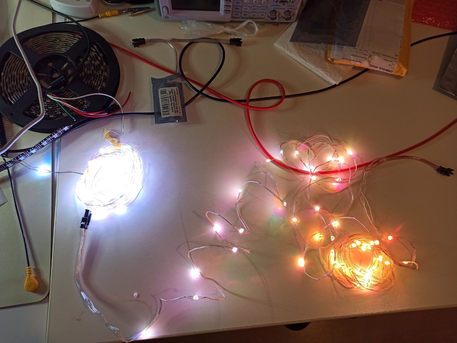
As you can see, the strip that is near the PSU is bright white as it should be, but the half of the next strip is starting to have discoloration and instead of white light you get yellow. That’s because the length of the strip adds more resistance in the end of the line and the voltage on the LEDs is dropped enough to not give full power to the LEDs, so you get a dim light (thus yellow).
The solution for that, as you may already have guessed, is to supply voltage to both ends of the strip. Therefore, the +5V PSU output is connected in both ends (you don’t have to connect both GND though, one is enough). The result is that now the stripe will have equal voltage in both sides, so all the LEDs will be lit the same. The next photo shows the 10 meter strip with the PSU connected to both sides.
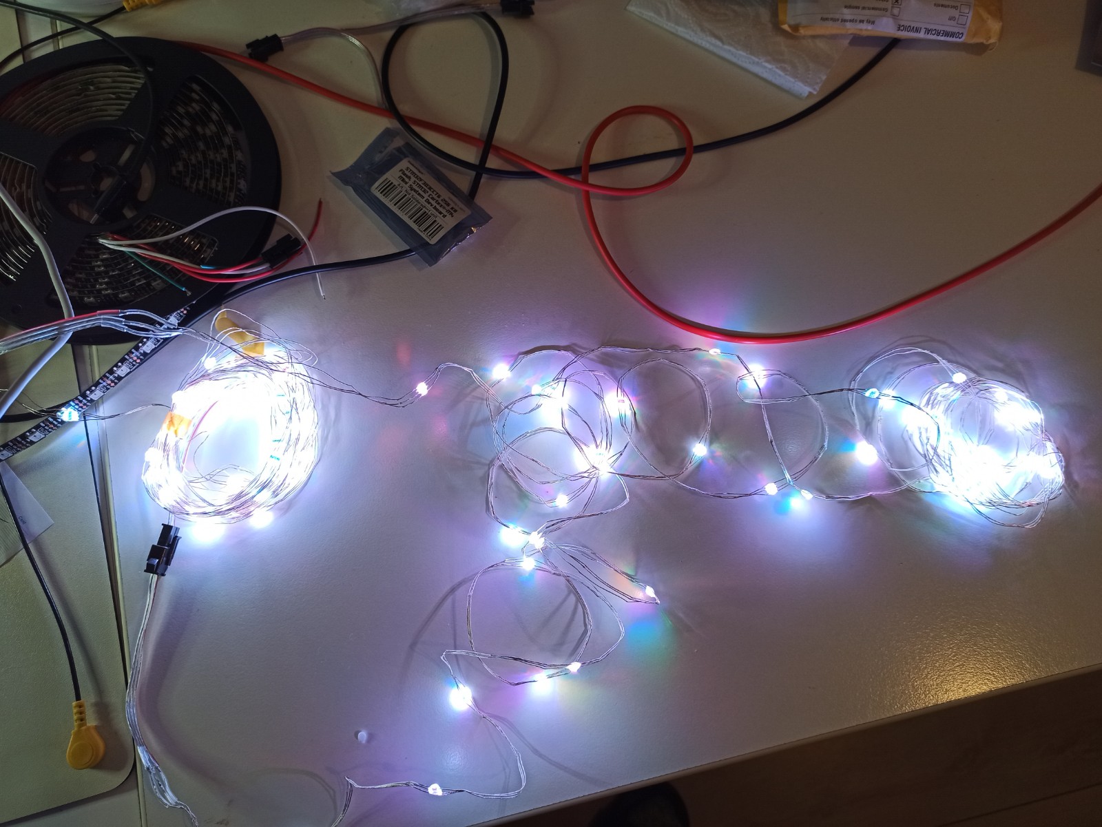
You see now that the light is uniform through the whole LED strip length.
Finally, I’ve measured the maximum consumption of the 10m LEDs strip when all color pixels (RGB) are boosted to the max value 0xFF. The result is:
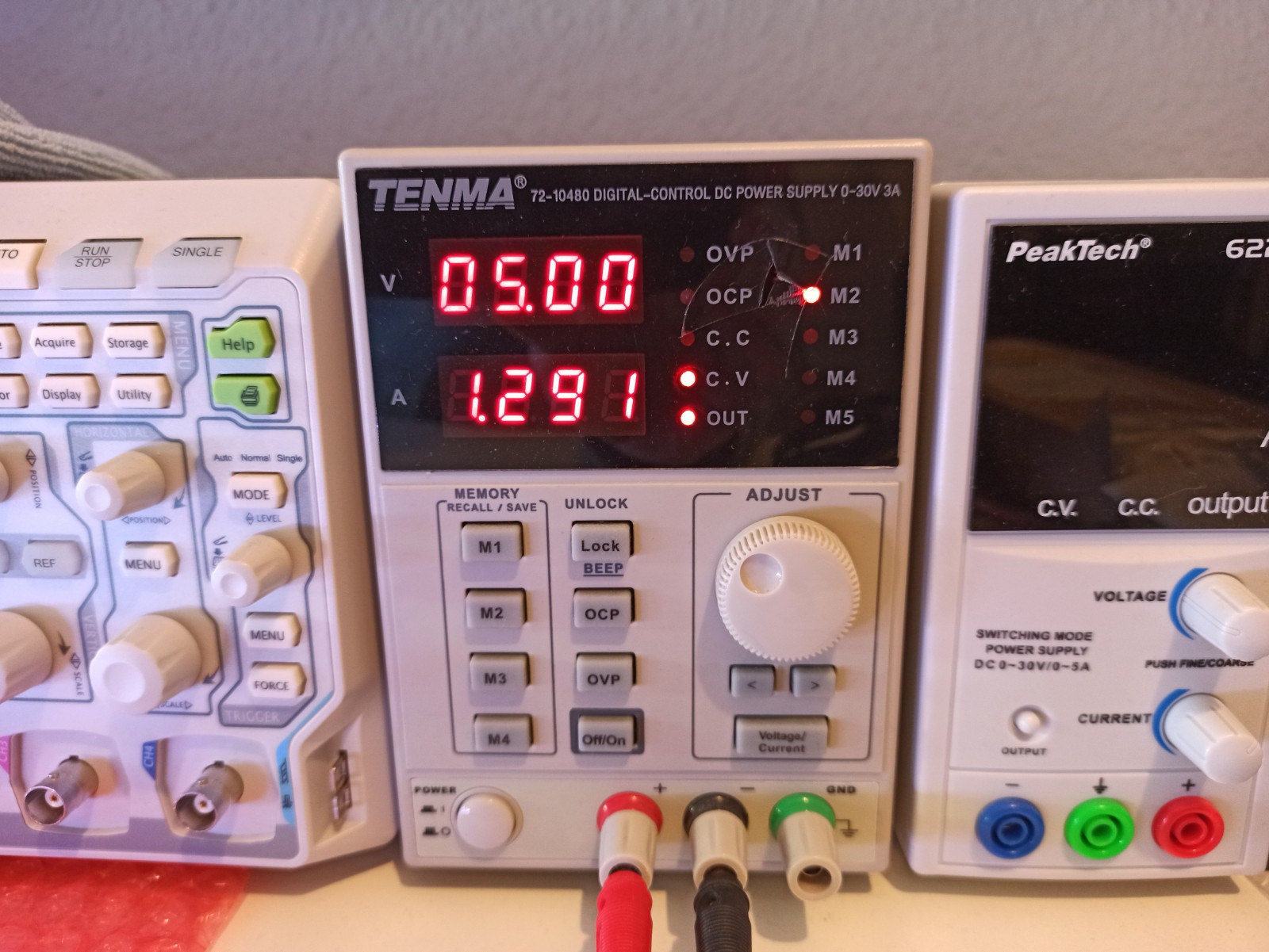
So, it’s about 1.3A @ 5V or 6.5W. Therefore a USB 5V/2A charger is more than enough for the strip including the ESP8266. I don’t plan to lit all the LEDs to full white at the same time anyways as I like dim lights. I just remind you here that you can use the ambient light functionality in the ESP firmware and light your organizer in any color to have a cool ambient effect in your lab.
Installing the LEDs
Next step is to install the LED strip in the back of the organizer. It seems to me that this was the most time consuming task compared to write the firmware… Anyway, since I have 3 organizers that I want to illuminate and each one has 33 drawers, it means I need 99 LEDs, so I got a LED strip with 100 LEDs with 1 LED / 10cm. The extra length is very convenient in this case.
Also, because I have 3 organizers and only 1 strip then it means that I had to cut the strip and solder connectors, so when I have to move them then I don’t have to remove the strip or remove them altogether. Also in case I need to add an extra organizer then I can extend the strip with another connector. Also using the WS2812B is nice because one of the LEDs is malfunctioning I can replace it easily.
One last thing is to decide the LED indexes before you fill the DB. I should probably mention that earlier, but I guess you’ll read that far before doing any of the previous steps. Let’s see a simplified example of how I’ve laid out the LED strip in the back of the organizers
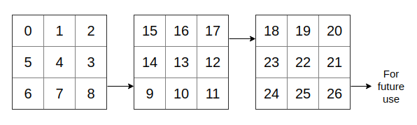
The above diagram shows a simplified diagram of the 3 organizers and the index increment direction for the LED indexes. It’s obvious that it doesn’t make much sense to label each drawer like that if you were using a sticker on each drawer and write an index with a marker. But it makes perfect sense in case you have a LED strip like the WS2812B, because that way you minimize the length of the strip. Of course you can use a different arrangement like start from top-to-bottom instead of left-to-right. In my case I’ve used a quite unusual indexing as you’ll see in the next picture thatI’ve done with the one of the organizers.
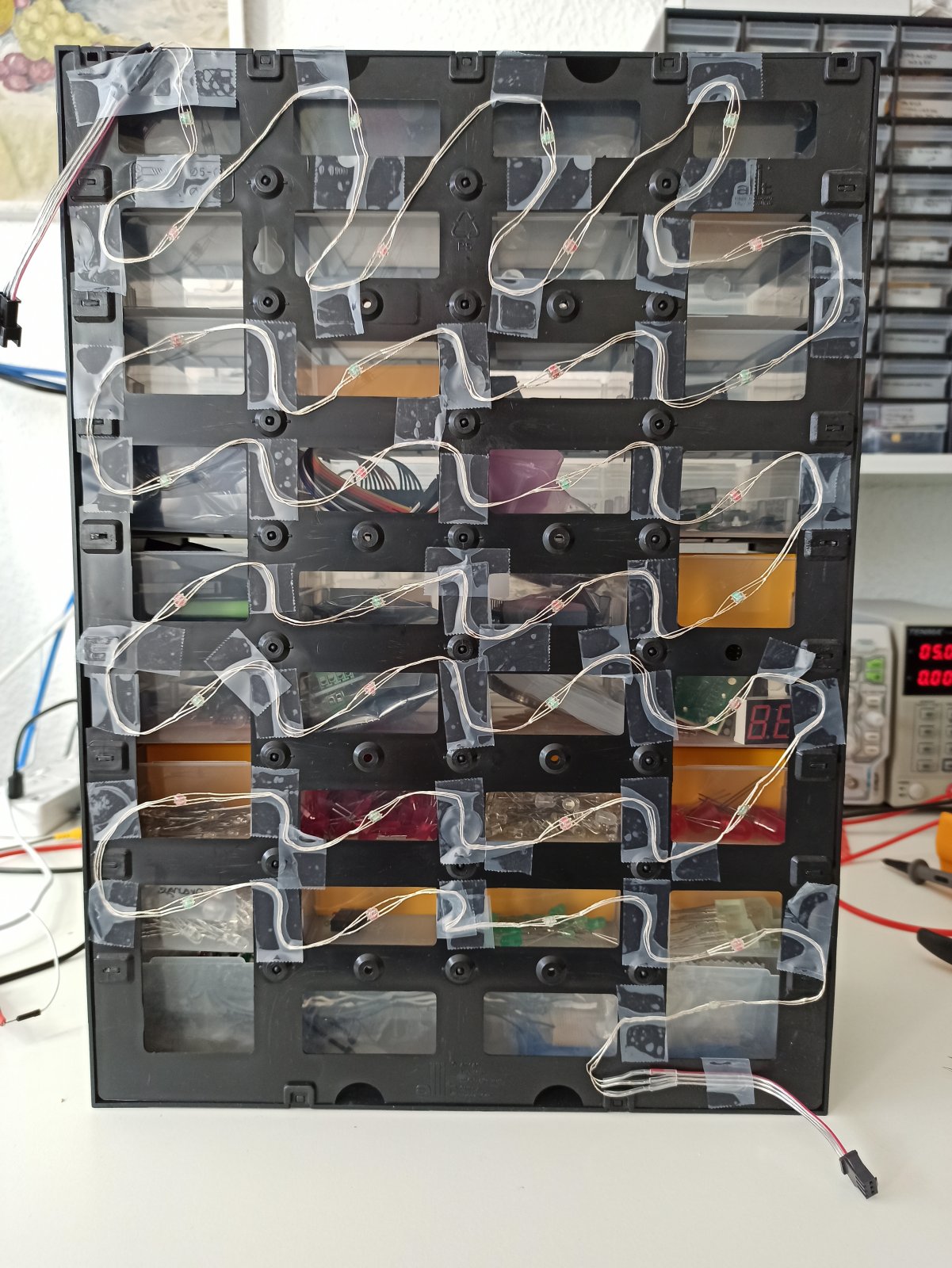
Let me say here, that for my standards it’s the best I could do. I’m getting really bored and lazy when it comes to manual work like this, so I’m just doing everything as fast as I can and never look back again (literally in this case).
As you can see there’s a single LED behind each drawer and I’ve used an invisible tape to stick the flexible strip on the plastic rails in the back. I hope they won’t fell soon, but generally I’ve used tons of invisible tape for various reasons and it never failed me. Also, look the the indexing on the top it doesn’t make sense, especially with the indexes I’ve used in the previous example. The reason for that is that only this way the input was because it was more convenient in order to connect the next strip. This is a calc sheet I’ve made. It probably doesn’t make sense but the teal color represents the left organizer, the violet the middle and the orange the right organizer. Then (ABC) is the first column of the organizer, (DEF) the second, (GHI) the third and finally (JKL) is the fourth column of drawers. Yeah I know, my brain works a bit weird, but I find this very easy to understand and remember what I’ve done.
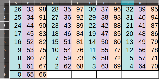
Anyway, you don’t have to use this, you can skip it and make an indexing map that is better for you.
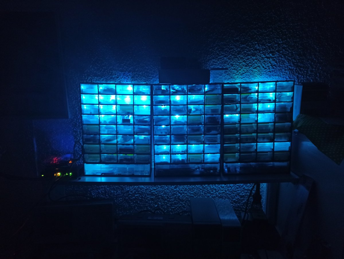
Now, this is a photo of the back of all 3 organizers when I’ve done with this ridiculous amount of boring manual work…
At least it worked without any issues on the first boot. As you may see I had to cut the strip at every end and solder connectors and also had to solder the two catted pieces from the long strips to make the strip part for the last organizer. Oh, so boring!
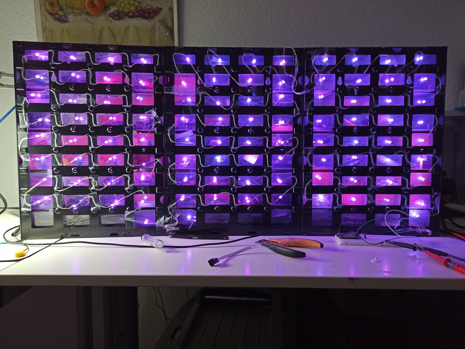
In the above ans also the next picture I’ve tested the ESP8266 and the strip with the indexes and the ambient functionality. This is after I’ve finished with the whole installation.
Neat. Of course, you wouldn’t expect to have uniform Illumination as each drawer has different components, some they’re full, some almost empty. But still the result in really nice and actually it looks better in my lab than the picture.
Finally, I’ve also made a custom USB cable to provide power to both the ESP8266 and the WS2812B strip. I’ve used a USB power pack that is capable to provide 2A @ 5V, which is more than enough for everything. This is the cable.
Next thing I’ll do when I get my 3D printer is to print a nice case to fit the ESP module.
Installing the web-interface to BPI-M1
In may case, after everything seems to be working I’ve moved the whole www/lab folder from the repo to the BPI-M1. As I’ve already mentioned I’m using the Armbian distro on my BPI-M1, which doesn’t have a web server, PHP and sqlite by default. Therefore, I’ll list the commands I’ve used to install those in Armbian. So, to install lighhtpd with php and sqlite support, I’ve run those commands:
1
2
3
4
5
6
apt-get update
apt-get upgrade
apt-get install lighttpd php7.2-fpm php7.2-sqlite3 php-yaml

lighttpd-enable-mod fastcgi
lighttpd-enable-mod fastcgi-php
Then edit the 15-fastcgi-php.conf file
1
vi /etc/lighttpd/conf-available/15-fastcgi-php.conf
and add this:
1
2
3
4
5
6
7
8
9
10
# -*- depends: fastcgi -*-
# /usr/share/doc/lighttpd/fastcgi.txt.gz
# http://redmine.lighttpd.net/projects/lighttpd/wiki/Docs:ConfigurationOptions#mod_fastcgi-fastcgi

## Start an FastCGI server for php (needs the php5-cgi package)
fastcgi.server += ( ".php" =>
    ((
        "socket" => "/var/run/php/php7.2-fpm.sock",
        "broken-scriptfilename" => "enable"
    ))
Then uncomment this line in /etc/php/7.2/fpm/php.ini
1
cgi.fix_pathinfo=1
And finally restart lighttpd
1
sudo service lighttpd force-reload
Now copy lab/ folder from the www/ in the repo to the /var/www/html folder, so the index.php file now should be in /var/www/html/lab/index.php.
Finally, you need the right permissions in the web folder, so run this command in your SBC terminal (via ssh or serial console)
1
sudo chown www-data:www-data /var/www/html/lab
Now use any web browser (smartphone, laptop, e.t.c.) and connect to the web interface and test again that everything is working fine. Also test that the upload is working with large pdf files. In case it doesn’t then have a look in the www/php.ini file and add those params to your SBC, too.
If it’s working, then you’re done.
Demo
Here is a video with playing around with the web interface and also a video that I’m using the web browser on my workstation to enable the ambient feature of the ESP8266 firmware, which just lids all the WB2812B strip LEDs to a color and makes a nice color-power-consuming atmosphere in my home lab.
In the first few minutes I’m just fooling around with the database and I’m searching for MCP and STM keywords in there. I’m also using the Show button to demonstrate that the LED of the drawer that contains the part is lit. Then I test the ambient light function with my smartphone and finally with the workstation browser.
Generally, I’m always using my workstation and never the smartphone. The difference in the two cases is that when the web interface runs on the workstation then the color HTML object changes the color in real-time while you’re moving your mouse and you don’t have to press set every time (which you need to do with the mobile browser). You can see that at 3:13 of the video. In the code you can see two javascript events, ambient_color() and save_ambient_color(). The first event is called with the oninput callback, which means on any color update in real-time from the HTML color object and the second event, which is the onchange() is triggered only when you close the color picker on the desktop web-browser or click set on the mobile browser. In the case of the onchange() event the color is also saved in flash, so next time you press the Enable ambient button then this color is used.
Some weird issues
During my experiments I had some weird behavior from a specific batch of ESP8266 modules. It seems that not all modules are made the same. These are the two modules I’ve used
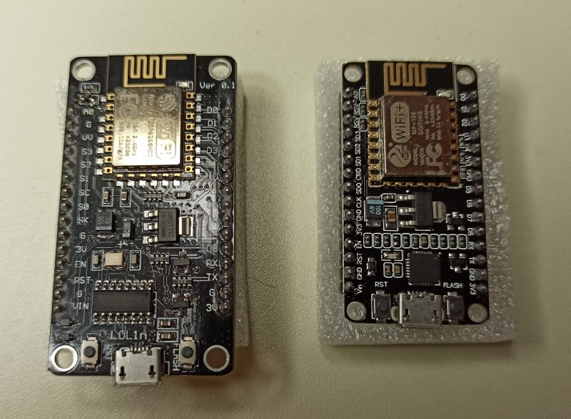
On the left side is the LoLin NodeMCU module and on the right side is a generic cheap module I’ve bought from ebay some time ago with this description here: NodeMCU ESP8266 ESP-12E V1.0 Wifi CP2102 IoT Lua 267 NEW.
The problem I had is that when I flashed the same firmware on both devices the generic ESP8266 module was jamming my smartphone WiFi connection, but the LoLin didn’t had any affect. The next image shows the affect both modules have on a Speedtest run.
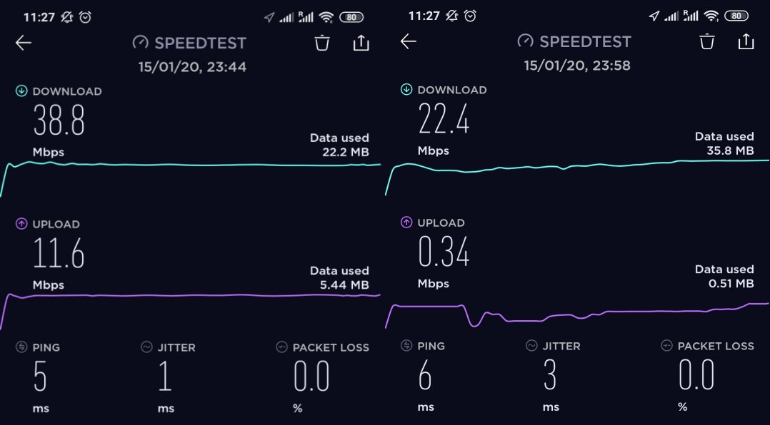
On the left side is when the firmware is running on the LoLin module and the right when it’s running on the other. You see that the difference is quite large, but the worst thing is that in the second case it was making the internet browsing with my smartphone very hard as I couldn’t download web pages fast and it was lagging a lot.
First thing I thought was the transmitting power. I believe that the second module transmit power is quite high and thus creates those issues. I thought to use my RTL-SDR (that I’ve used in this post here), but the problem with this dongle is that the Rafael Micro R820T/2 tuner is able to tune up to 1766 MHz, which makes sniffing the 2.4GHz band impossible. I’ve searched and found an MMDS downconverter in aliexpress but that doesn’t ship to Germany and the other options where quite expensive, so I’ve dropped the idea to get into it and find what’s going on. At some point I’m planning to get a HackRF One anyways, which is able to sniff up to 6GHz, so I may look into it again then.
Anyway, just have that in mind because it may cause troubles in your WiFi network. For the ESP8266 arduino framework there’s also the setOutputPower() function that is supposed to control the TX power from 0 up to 20.5dBm (see here). I may play around with it also at some point, but for now I’m using the LoLin module.
Generally, I’ll have a look at it in the future and write a post when I figure out why this is happening. I have 3 of those ESP8266 modules and it’s a shame to be unusable. I’ll try experimenting first with the setOutputPower().
Edit 1:
I’ve just realized that the default behavior for WiFi.begin() is to configure both STA + AP, which means that ESP8266 is configured as both access point (AP) and client/station (STA). This is definitely an issue and affects the overall WiFi performance of the surrounding devices, but still doesn’t explain the difference between the different modules. Anyway, now I’m forcing only STA by explicitly setting the mode in the code
1
WiFi.mode(WIFI_STA);
Edit 2:
After forcing the STA mode, the speedtest got a bit better on my smartphone but still the uploading was horrible. Next was to limit the TX power with the WiFi.setOutputPower() function. This solved mostly the issues I had, but not completely. So, around 6-8 dBm I’ve seen a couple of disconnections on the ESP8266 while I was running the speedtest on the the smartphone. Anyway, around 12.5 dBm seems the sweet spot for my home arrangement, but still not quite happy with the upload speed on the speedtests.
For now I’ve ordered a couple more LoLin modules, because I only have one that seems to be working fine. All the other modules have this issue. When I get the HackRF or if I find a MMDS downconverter I’ll get deeper into this…
Conclusions
This post ended up longer than I expected. Although all the different parts and codes are simple, it’s just that there are many different things that compose the outcome. Also I got a bit deeper with the development and testing tools (e.g. docker). Sometimes I tend to think that I’m using Docker too much, but on the other hand I’m happy that I keep my development workstation clean from tons of packages and tools that I don’t use often, but only when making those stupid projects.
Regarding the project, I have to say that for me this DB was a savior for me, because many times I need components and I don’t know if I have them and even more I have no idea where to start looking for them. Generally, I keep things organized otherwise it would be impossible to keep track of every component, but no matter how organised I am, even if I find that I have what I need in the database, then if I don’t remember -which is the case most of the times- where the component might be, then I need to start looking everywhere.
For that reason making this interactive RGB LED strip to point to the correct drawer is a huge advantage for me. Sometimes now I just play with this even if I don’t really need a component, he he. It’s really nice to have.
On the other hand, if you’re thinking to implement this, then you’re free to use the code and do whatever you like with it. The only boring thing is to feel the database if you have a lot of components, but you don’t have to do it in one day. I’m filling this database for the last 6 years. What I do is, first I buy the components from ebay (usually) and then I find a nice image and the datasheet and I add the component to the database.
Here’s a nice trick I’m using in some components. Since the thumbnail doesn’t have to be same image with the image in the image/ folder, what I do is that I’m using a different image in thumb/ and image/ folder. In this case, when the list is shown the thumbnail image is shown and then when I click on the image then the image from the image/ folder is displayed. This is useful for example in many MCUs, because I use an actual photo of the MCU for the thumbnail and the pinout image for the bigger image.
Another useful thing that I do, is that many times I can’t find a datasheet for the component but I’ve found a web page that has info for that component. Then I print the web page in a PDF file and I’m uploading that. Finally, some times I need to save more than one PDF for a component, therefore in this case I merge two or more PDF files in one using one of the available online PDF mergers (e.g. this or that). That way I can overcome the fact that only one PDF is available for each component in the database.
Finally, what you’ll learn by doing this project is work with docker images and web servers, setting up your SBC as a web server, a bit of REST (although aREST is not really a RESTful environment), and also a bit of PHP, javascript, SQLite, ESP8266 firmware and playing with LEDs.
That’s it, I hope you find this stupid project useful, for some reason.
Have fun!
Comments powered by Disqus.