Control RGB strip with WiFi (ESP8266) and arduino.
Intro
This is my first stupid project posted here. I wanted to put some color in my living room and these inexpensive RGB led strips that you can find in ebay are perfect for this. To control RGB strips is done easily today. You just need a small micro-controller and an RGB led driver. So, the only thing that remains is to find a way to do that remotely and also be able to control several RGB strips at the same time. But let’s have a look at the components that I’ve used.
Components
RGB strip(s)
You’ll need an RGB strip to control, of course. You can find a plethora of RGB strips in ebay, just search for led strip 5050 and you’ll get tens of thousands results. Just pick one for your needs, waterproof, low or high power e.t.c. Choose a 12V strip. You’ll also need a 12V power supply for that, so buy one that meets the power consumption of the strip. If you don’t know what’s the power consumption ask the seller and he’ll provide you with the correct one.
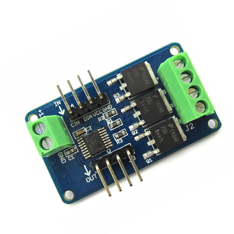
RGB led driver (P9813)
The RGB led strips are controlled with an RGB driver with the P9813, you can find them in ebay by searching for RGB LED Strip Driver Module Shield. This driver is quite nice and cheap (~$4.50) and supports chaining. You won’t need that now, but it’s a good to have option for other projects. This is how it looks like
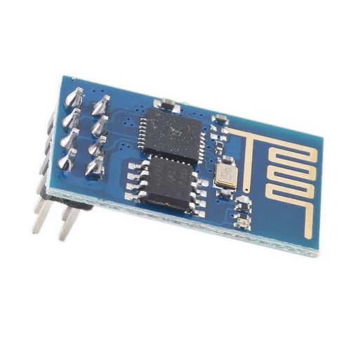
ESP8266
Well, you’ll find out that I love using the ESP8266 modules, as it’s easy to modify the source code with the SDK and also you can use any network capable device to interact with them. I’ll write a separate post about ESP8266 in the future and how you can write your own code for these modules. You can find them cheap in ebay and they cost around $2.50. There are a few types of this module that they have a different flash size (512KB, 1MB), but the only thing that you should care about now is that it needs to support 9600 baud rate and not only 115200, because I’m using a software serial library for the arduino that behaves much better on lower baud rates. Be aware that ESP8266 is a 3V3 only device. This is the module
Arduino mini
For this project I’m using an Arduino mini to control the RGB driver and the ESP8266. You can use any arduino board that you may have, like UNO, as it’s easier to flash them without any need for a usb uart module. I’ve just use the mini because its small factor and also it’s 3V3, which helps a lot with the ESP8266 as you won’t need a level converter.
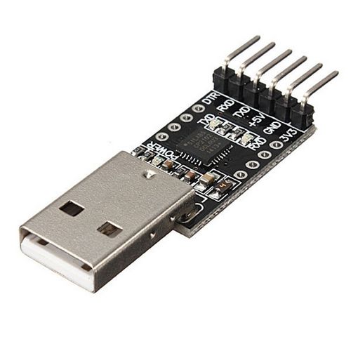
USB-uart module
To flash the arduino-mini you’ll need a USB uart module that has a DTR output. This is needed in order to reset the arduino to the bootloader mode and load the binary. You can find these cheap on ebay (~$1.50) and it looks like that
Raspberry-pi (or something similar)
In this project I wanted to use my smart-phone, tablet or desktop to control the RGB colors; therefore, a simple web interface was ideal for that purpose. The web interface is running on a banana-pi sbc in my case, but you can use a raspberry pi or any other board/computer that is able to run a php-enabled web server.
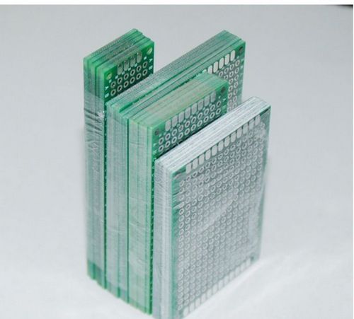
Other
You’ll also need a small pcb board to solder everything on it, then power supplies for each RGB strip and a power supply for each arduino. While building the project you can use a breadboard and some breadboard jumper cables to connect everything and test that it works. You can find prototype PCB board like these on ebay.
Making the stupid project
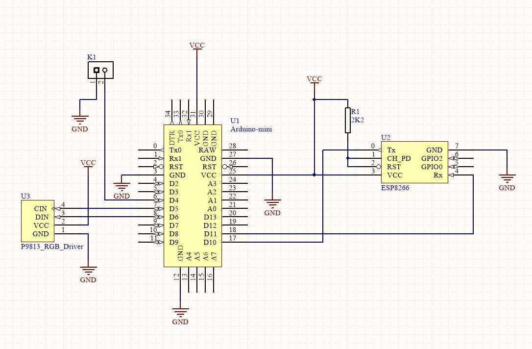
Although I haven’t build any PCB for this, the schematics are needed to connect the parts together. K1 is a jumper that is used to select the operation mode as the arduino firmware supports two modes, one for configuration and one for normal operation. The rest connections are self-explained.
After you done with connecting the parts, you need to connect the USB to uart adapter to arduino mini and apply a 3V3 power to the circuit. Then you need to download this git repo and build the code with arduino IDE or any other tool you prefer (I use sloeber).
https://bitbucket.org/dimtass/arduino_wifi_rgb
Build the code, upload the firmware to arduino and remove the power.
Then connect the RGB strip to the P9813 driver and apply 12V to the block connector (J1).
Make sure all connections are correct and place the short jumper to the K1 pin header that shorts D4 to the GND. This will put the firmware to configuration mode.
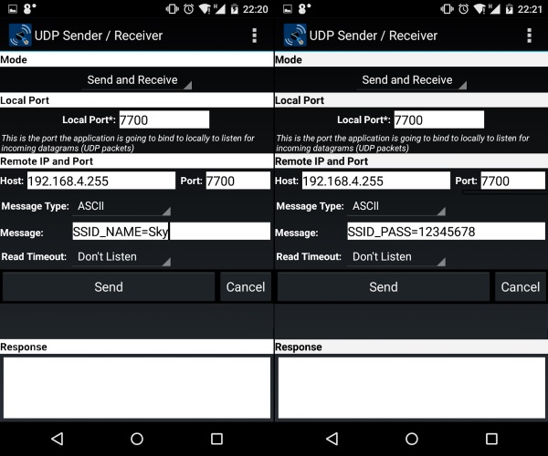
In the configuration mode, the ESP8266 is configured as an AP. You can connect to this AP with your mobile or laptop and configure the connection settings that ESP8266 needs in normal operation. In normal operation the firmware will try to connect to your wireless router with the SSID and password you provided during configuration mode. To configure these settings you need to send a few commands using a UDP client. You can either use hercules utility (or any windows/linux udp desktop client you like) or your mobile. I’ve used an android app which called UDP Sender/Receiver.
After you connect to the ESP8266 AP, you’ll get an IP in the subnet 192.168.4.xxx and the ESP8266 will have the IP 192.168.4.1. Now you need to send the UDP commands in the broadcast IP 192.168.4.255 and port 7700. Therefore, if your router’s SSID is Sky and the password is 12345678, then to configure the SSID send to UDP port 7700 the following command:
1
SSID_NAME=Sky
and to configure the password send this command
1
SSID_PASS=12345678
Finally, remove the jumper to enable the normal mode and reset the power from the board or send this UDP command
1
RESET
This is an example if you use your smart-phone.
After the reset, the board will try to connect to the wifi router using the parameters you programmed in the configuration mode. At any time you can use the USB to uart module to retrieve the trace messages from the board (115200 baud-rate).
Now copy all the files from the www/rgb folder to your web server. For this I’m using a banana-pi, which is also serves me as my network file server and hosts several other stupid things, like a web server for the home automation, my components database, e.t.c. At this point you need to make sure that ESP8266 is always assigned the same IP, otherwise everytime your router reboots, then it will get a different IP, which is very inconvenient as you need to change this every time in the web server configuration. So, in the functions.php file of the web interface change the $remote_ip with the IP address that of the ESP8266. You can see the IP either from the trace messages in the uart or from your router.
So, you’re ready to go. In my case the web app is in the following address http://192.168.0.100; therefore, when I type this address in my smart-phone’s web browser I get the following web interface
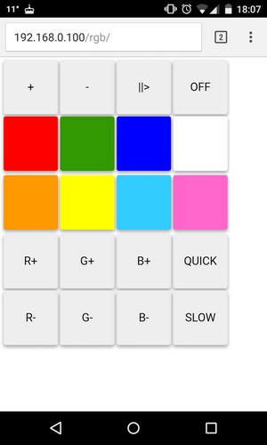
This is a brief explanation of each button:
+: Dim up-: Dim down||>: Start/pause the random RGB colorsOFF: Power off strip (sends 0x00 to all colors)R+/-: Increase/decrease red levelG+/-: Increase/decrease green levelB+/-: Increase/decrease blue levelQUICK: Increases the speed that the random colors are changingSLOW: Decreases the speed that random colors are changing
The rest of the buttons are just 8 pre-defined colors. There’s a catch here. There isn’t any RGB strip that has completely calibrated colors, so if you think that you send something like HTML color values and you get the same color from the strip, then think again. You need to manually calibrate your strip. To do that, you have to open the rgb_buttons.json file in the web app and change the values for the 8 pre-defined color buttons. These buttons are from btn_5 to btn_12.
Here is a brief explanation of this json file:
name: it’s the button’s name. Don’t change this.color: this is the display color of the button on the web appfunction: when it’s set to color it means that contains color datadata: these are the real RGB values that the P9813 driver will use and they have this format #RRGGBB, which is a HEX byte for each color.text: the text displayed on the button
This is a sample video of this stupid project on action.
Have fun!
Comments powered by Disqus.