Nanopi-R4S benchmarks with networking optimizations
Intro
In the last post, I’ve done a benchmark on the Nanopi-R2S and Nanopi-R4S. After a comment from tkaiser here, I’ve verified that all IRQs are mapped to CPU0, which means that the default FriendlyWRT images are not optimized. Those optimizations though are easy to make and in this post I will guide you through those optimizations and also present the results and make a comparison with the default images.
SMP IRQ Affinity
The SMP IRQ affinity is a functionality in the Linux kernel that allows the user to control which CPU handles the IRQ of a certain device that comes from the interrupt controller. In multi-core CPUs that makes a lot of sense, because the user can change the default behavior of the kernel which puts all the effort to CPU0. Therefore, with the SMP IRQ affinity the user can use a bit mask and control which core handles specific interrupts.
Hence, the process has two stages. The first is to find the interrupt number of the device you want to move its IRQ handling to another core. The second step is to set a proper bit mask to the smp_affinity mask of the specific interrupt. This mask will be used to forward the IRQ handling to the CPU core you want.
Another important reason for the user to control the SMP affinity manually is that in multicore SoCs like the RK3399 which include core with different architecture, there might be a chance that the more powerful cores are not used properly by default from the kernel. And actually this is the case with the RK3399, because in this case the CPU0 is a Cortex-A53 from the quad configuration which is clocked at 1.4GHz and therefore the faster dual Cortex-A72 which is clocked at 1.8GHz is staying idle.
Receive Packet Steering (RPS)
The RPS is very well explained here, but I will try to simplify it a bit more. RPS is a functionality in the kernel that -in multi-core systems- distributes the workload of network packet handling to different cores in order to speed up the process. This might not be so important for your desktop, but for a router -like the Nanopi-RxS- it’s very important to be able to tweak that and be able to set a specific core for the task.
Again, the RPS is a bit mask that controls which cores are in the kernel’s distribution list, but you can also set a single core for that. Therefore, one of the optimizations we can do is to assign a specific core -preferably one of the fast cores- for that.
FriendlyWRT
In this post for both Nanopi-R2S and R4S I’m using the custom FriendlyWRT distro from FriendlyElec. This is the version for Nanopi-R2S:
1
Linux FriendlyWrt 5.4.61 #1 SMP PREEMPT Fri Sep 4 15:12:58 CST 2020 aarch64 GNU/Linux
And this is the version of Nanopi-R4S:
1
Linux FriendlyWrt 5.4.75 #1 SMP PREEMPT Tue Nov 10 11:13:15 CST 2020 aarch64 GNU/Linux
Nanopi-R4S optimizations
Hopefully the above explanations are quite clear, so I’ll explain now what are the two optimizations that you need to do and how to do them. The Nanopi-R4S is based on the RK3399 SoC which is a dual Cortex-A72 core and a quad Cortex-A53. In FriendlyWRT the A72 is clocked at 1.8GHz and the A53 at 1.4GHz. Generally, the core clocks are not something that is controlled only from the CPU itself, but in Linux the min and max clock speeds are defined via the device-tree when the kernel loads. Therefore, the max rated clock for the A72 might be 2.0GHz, but that doesn’t mean that this will be the max clock on every OS and therefore, as I’ve mentioned in case of FriedlyWRT the max clock is set to 1.8GHz.
So, the first optimization is to assign the interrupt handling of the eth0 and eth1 interfaces to another core than CPU0 and preferably to the fastest cores. To view the CPU frequency for each core you can use the following command:
1
2
3
4
5
6
7
root@FriendlyWrt:~# cat /sys/devices/system/cpu/cpu*/cpufreq/cpuinfo_max_freq
1416000
1416000
1416000
1416000
1800000
1800000
From the above result we see that CPU0-3 is the Cortex-A53 and CPU4-5 is the Cortex-A72. Therefore, by default all IRQs are served by CPU0, which is the slower core and thus this can create an artificial bottleneck, since there are 2 fast cores sitting there and doing nothing.
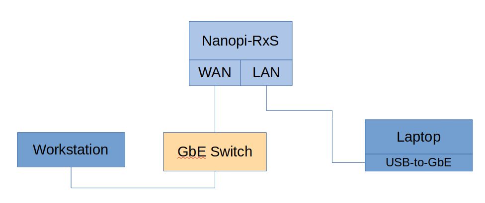
Next step is to figure out which are the IRQ numbers for eth0 and eth1. To do that I first run a iperf test with my Laptop as a client and connected on the LAN port of the Nanopi-R4S and my workstation as a server and connected on the WAN port.
Then I’ve printed the /proc/interrupts to view the number of IRQs and this is the result.
1
2
3
4
5
6
7
8
9
10
11
12
13
14
15
16
17
18
19
20
21
22
23
24
25
26
27
28
29
30
31
32
33
34
35
36
37
38
39
40
41
42
43
44
45
46
47
48
49
50
51
52
root@FriendlyWrt:~# cat /proc/interrupts
           CPU0       CPU1       CPU2       CPU3       CPU4       CPU5
 15:      59197      27202      24660      23678      44323      32887     GICv3  30 Level     arch_timer
 17:       2733      16708      15550       8386      12996      11459     GICv3 113 Level     rk_timer
 18:          0          0          0          0          0          0  GICv3-23   0 Level     arm-pmu
 19:          0          0          0          0          0          0  GICv3-23   1 Level     arm-pmu
 20:          0          0          0          0          0          0     GICv3  37 Level     ff6d0000.dma-controller
 21:          0          0          0          0          0          0     GICv3  38 Level     ff6d0000.dma-controller
 22:          0          0          0          0          0          0     GICv3  39 Level     ff6e0000.dma-controller
 23:          0          0          0          0          0          0     GICv3  40 Level     ff6e0000.dma-controller
 24:          1          0          0          0          0          0     GICv3  81 Level     pcie-sys
 26:          0          0          0          0          0          0     GICv3  83 Level     pcie-client
 27:   10628015          0          0          0          0          0     GICv3  44 Level     eth0
 28:      28962          0          0          0          0          0     GICv3  97 Level     dw-mci
 29:          0          0          0          0          0          0     GICv3  58 Level     ehci_hcd:usb1
 30:          0          0          0          0          0          0     GICv3  60 Level     ohci_hcd:usb3
 31:          0          0          0          0          0          0     GICv3  62 Level     ehci_hcd:usb2
 32:          0          0          0          0          0          0     GICv3  64 Level     ohci_hcd:usb4
 33:          0          0          0          0          0          0     GICv3  94 Level     ff100000.saradc
 34:          0          0          0          0          0          0     GICv3  91 Level     ff110000.i2c
 35:          0          0          0          0          0          0     GICv3  67 Level     ff120000.i2c
 36:          0          0          0          0          0          0     GICv3  68 Level     ff160000.i2c
 38:        106          0          0          0          0          0     GICv3 132 Level     ttyS2
 39:          0          0          0          0          0          0     GICv3 129 Level     rockchip_thermal
 40:       3231          0          0          0          0          0     GICv3  89 Level     ff3c0000.i2c
 41:          0          0          0          0          0          0     GICv3  88 Level     ff3d0000.i2c
 44:          0          0          0          0          0          0     GICv3 147 Level     ff650800.iommu
 45:          0          0          0          0          0          0     GICv3  87 Level     ff680000.rga
 47:          0          0          0          0          0          0     GICv3 151 Level     ff8f3f00.iommu, ff8f0000.vop
 48:          0          0          0          0          0          0     GICv3 150 Level     ff903f00.iommu, ff900000.vop
 49:          0          0          0          0          0          0     GICv3  75 Level     ff914000.iommu
 50:          0          0          0          0          0          0     GICv3  76 Level     ff924000.iommu
 51:          0          0          0          0          0          0     GICv3  55 Level     ff940000.hdmi
 65:          0          0          0          0          0          0  rockchip_gpio_irq   5 Edge      GPIO Key Power
 67:          0          0          0          0          0          0  rockchip_gpio_irq   7 Edge      fe320000.dwmmc cd
113:          0          0          0          0          0          0  rockchip_gpio_irq  21 Level     rk808
114:          0          0          0          0          0          0  rockchip_gpio_irq  22 Edge      K1
166:         16          0          0          0          0          0  rockchip_gpio_irq  10 Level     stmmac-0:01
220:          0          0          0          0          0          0     GICv3  59 Level     rockchip_usb2phy
222:          0          0          0          0          0          0   ITS-MSI   0 Edge      PCIe PME, aerdrv
223:          0          0          0          0          0          0     GICv3 137 Level     xhci-hcd:usb5
224:          0          0          0          0          0          0     GICv3 142 Level     xhci-hcd:usb7
230:          0          0          0          0          0          0     rk808   5 Edge      RTC alarm
234:     855861          0          0          0          0          0   ITS-MSI 524288 Edge      eth1
IPI0:     11514     109149      55900      39843      31597     748488       Rescheduling interrupts
IPI1:       468       5518     259096     128778    4150594      21564       Function call interrupts
IPI2:         0          0          0          0          0          0       CPU stop interrupts
IPI3:         0          0          0          0          0          0       CPU stop (for crash dump) interrupts
IPI4:       976       2231       1880       1877       2373       2655       Timer broadcast interrupts
IPI5:     16670       6729       7059       4912      23162      13914       IRQ work interrupts
IPI6:         0          0          0          0          0          0       CPU wake-up interrupts
Err:          0
From the above output you can see that IRQ number 27 is mapped on the eth0 interface and IRQ number 234 is mapped to the eth1. Therefore, now we can use the proper bit masks to assign those IRQs to another core.
In this case, I’ll assign IRQ 27 to CPU4 (eth0) and IRQ 234 to CPU5 (eth1). Both CPU4 and CPU5 are the Cortex-A72 cores, the fast ones (1.8GHz). The same we need to do for the RPS for both interfaces. Gladly, the bit masks are the same for both cases (ethX and RPS), therefore the bit mask for eth0 is 0x10 and for eth1 is 0x20. This is because the following table.
| CPU5 | CPU4 | CPU3 | CPU2 | CPU1 | CPU0 | |
|---|---|---|---|---|---|---|
| eth0 | 0 | 1 | 0 | 0 | 0 | 0 |
| eth1 | 1 | 0 | 0 | 0 | 0 | 0 |
As you can see on the above table every cell is a bit, so we have 6 bits for 6 cores and therefore 01 0000 (=0x10 HEX) is the bit mask for eth0 and 10 0000 (=0x20) is the bit mask for eth1.
Then you need to create this script and make it executable.
1
2
3
4
5
6
7
8
9
#!/bin/sh
# CPU4 and CPU5 are the 1.8GHz cores
# Set CPU4 to handle eth0 IRQs
echo 10 > /proc/irq/27/smp_affinity
echo 10 > /sys/class/net/eth0/queues/rx-0/rps_cpus

# Set CPU5 to handle eth1 IRQs
echo 20 > /proc/irq/234/smp_affinity
echo 20 > /sys/class/net/eth1/queues/rx-0/rps_cpus
The first two lines are copying the mask to the smp_affinity -which controls in which core the IRQ is assigned- and to the rps_cpus, which controls in which core the network packet processing is done.
The next two lines do the same for the eth1 interface.
In FriendlyWRT you can add a service in /etc/init.d/ that calls this script if you like these changes to be effective when the system boots.
Nanopi-R4S benchmarks
In the previous post here, I’ve ran several benchmarks using iperf, but I found that the two benchmarks that are more demanding for the device is using two parallel threads for TCP and the UDP test, when both are done in both directions. This time I will also do this test using the default MTU which is 1500 and also test with 512 bytes, as this seems to be the size that various protocols prefer. The MTU size defines the largest packet size that will be transmitted over the network.
This change in MTU needs to be done on the iperf server and client, therefore in my case I had to use this command on my workstation and laptop.
1
sudo ip link set dev IF_NAME mtu 512
where, IF_NAME is the name of your network interface e.g. eth0, enp3s0, e.t.c. You can verify the size of the interface MTU with this command:
1
ip link list
The iperf server IP in these examples is 192.168.0.2 and the server is connected on the WAN port. The iperf client is 192.168.2.126 and it’s connected on the LAN port.
For the TCP test the commands I’ve used for the server and client are:
| Host | Command |
|---|---|
| Server (WAN) | iperf -s |
| Client (LAN) | iperf -c 192.168.0.2 -t 120 -d -P 2 |
For the UDP test the commands I’ve used for the server and client are:
Host | Command
- |- Server (WAN) iperf -s -u Client (LAN) iperf -c 192.168.0.2 -u -t 120 -b 1000M -d
Nanopi-R4S benchmarks
These are the results for the Nanopi-R4S with and without using the network optimizations and using 512 and 1500 MTU.
| MTU | TCP/UDP | Results Mbits/sec | Results Mbits/sec |
|---|---|---|---|
| (default) | (optimized) | ||
| 1500 | TCP | 941 | 941 |
| 1500 | UDP | 808 | 742 |
| 512 | TCP | 575 | 588 |
| 512 | UDP | 556 | (854) |
This is the /proc/interrupts after the benchmark, to verify the core assignment to the IRQs.
1
2
3
           CPU0       CPU1       CPU2       CPU3       CPU4       CPU5
 27:        152          0          0          0   22505343          0     GICv3     44 Level  eth0
234:        171          0          0          0          0    9048229   ITS-MSI 524288 Edge   eth1
Viewing those result, I don’t see any real benefit from assigning the the IRQ and RPS to the fast cores. The throughput seems to be the same. The last UDP result for the optimized case which is 854 Mbits/sec and it’s way faster than the non-optimized, is something that I don’t really trust, because I’m getting a weird warning when the test ends.
1
WARNING: did not receive ack of last datagram after 10 tries.
Also, I’m not getting any stats regarding the acknowledged received data and my gut feeling is that the UDP packets are actually lost when the MTU is set to 512. This I think needs more investigation, because it shouldn’t happen.
Therefore, given these results and ignoring the result in the parentheses, I would say that these optimizations don’t really benefit the network performance of the Nanopi-R4S.
Nanopi-R2S optimizations
It seems that the FriendlyWRT distro for the Nanopi-R2S is properly optimized by default and the eth0 IRQ is assigned to CPU1 and the xhci-hcd:usb4 is assigned to CPU2 as you can see here:
1
2
3
           CPU0       CPU1       CPU2       CPU3
 29:          0     473493          0          0     GICv2  56 Level     eth0
167:          0          0      81033          0     GICv2  99 Level     xhci-hcd:usb4
If you’re not aware the second GbE port of the Nanopi-R4S is a USB-to-GbE connected on a USB3.0 port, in this case in xhci-hcd:usb4.
For that reason I don’t see any point in to re-run the benchmarks for this case.
Conclusions
As I’ve mentioned, in my opinion the network optimization with the assignment of different cores for the network interface interrupts don’t really benefit the network performance of the Nanopi-R4S. I’m also not sure about the warning I’m getting with the last UDP test when the MTU is set to 512 where it seems that the data are actually getting lost, so I don’t consider this as a valid result.
Be aware that there might be other network optimizations which I’m not aware of, so this post might be incomplete.
Also the nice thing is that the FriendlyWRT distro for the Nanopi-R2S seems to have those optimizations already in place.
Personally, I would add those optimizations described in this post also on the Nanopi-R4S, because it makes total sense to have them there. Keep in mind that in this test the device is just running the default distro stuff, so there’s no external hard drive connected, no extra services e.t.c. But normally, on a system that is fully utilized there will be more services that run in the background, therefore it’s a good strategy to have those optimizations anyways.
In any case, personally I like the Nanopi-R4S and I find that it’s performance is good enough for my needs. Hope this post helped if you own the device.
Have fun!
Comments powered by Disqus.